7. General purpose PID
7.1 Introduction
The general purpose PID controllers are principally similar to the PID controllers for AVR and governor output. They consist of a
proportional, integral and derivative part, and the integral and derivative parts are dependent on the proportional gain. A functional
description of the principle can be found in the chapter about controllers for AVR and governor. The GP PIDs are slightly less
responsive, though. They are meant for purposes such as temperature regulation, controlling fans, valves, and so on. The principle
of relay control is also described in the chapter about AVR/governor control. Configuration of the GP PIDs is documented by
describing the possibilities of the GP PID interface, and with examples of configuration for different purposes.
Acronyms
• GP: General Purpose
• SP: Set Point
• PV: Process Variable
7.1.1 General purpose PID analogue loop
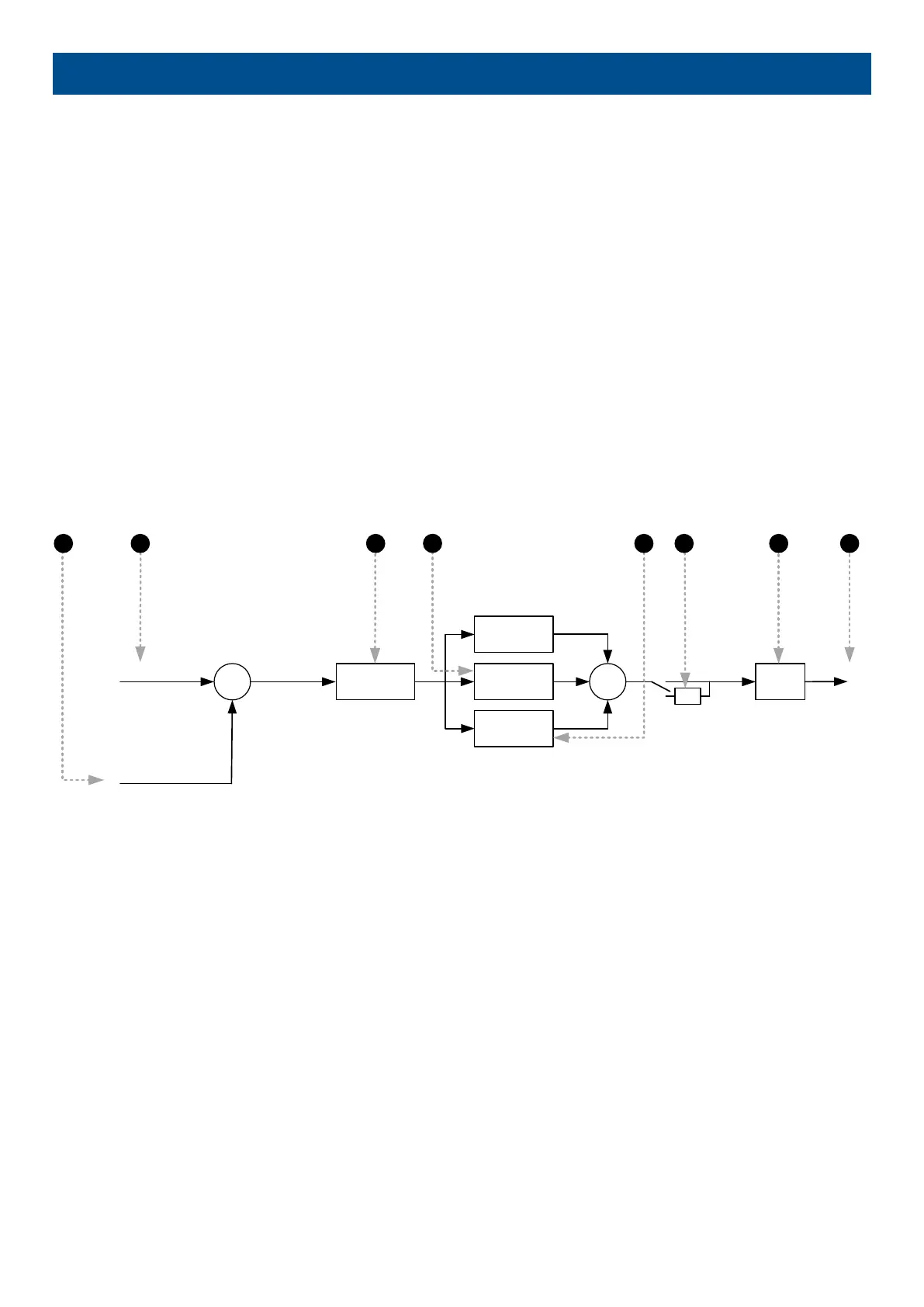
The analogue regulation in the general purpose PIDs is handled by a PID loop. The diagram below shows which elements the PID
loop consists of.
+
-
Kp
1
Ti
Td
∑
+
+
+
-1
Offset
Output
Input
Reference
3 7 821
4
65
1. Input: This is the analogue input that measures the process the controller is trying to regulate. See under Input later in this
document for more details.
2. Reference: This is the set point that the controller is trying to bring the input to match. See under Input later in this document for
more details.
3. Kp: The proportional gain of the PID loop. See under Output later in this document for more details.
4. Ti: The integral gain of the PID loop.
5. Td: The derivative gain of the PID loop.
6. Inverse: Enabling inverse will give the output a negative sign. See under Output later in this document for more details.
7. Offset: The offset is added on the function and displaces the regulation range. See under Output later in this document for more
details.
8. Output: This is the final output from the PID, controlling the transducer.
7.1.2 GP PID interface in USW
Configuration of the GP PID’s input and output settings is done with the “PID” interface in the DEIF USW, it cannot be done from the
display of the controller.
DESIGNER'S HANDBOOK 4189341275A EN Page 182 of 196

 Loading...


