INFO
If a step-down transformer is mounted with a genset controller, the settings shown in the table above should also be used.
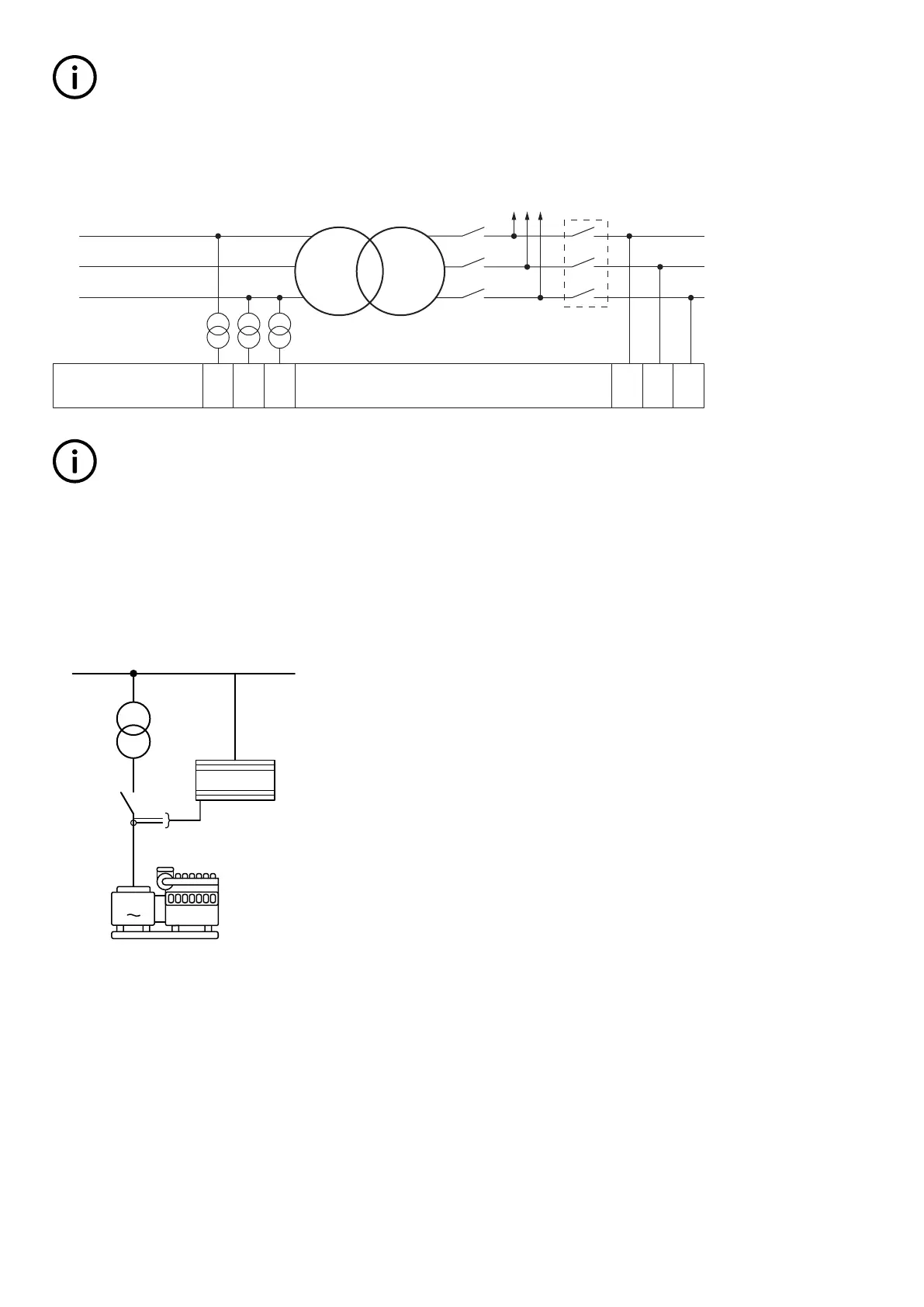
If a step-down transformer and mains controller are mounted, note how the measurements are mounted on the controller. The
correct connection is shown below.
Busbar
2L1
2L2
1L2
1L1
HV LV
MB
2L3
1L3
Mains
Load
TB
optional
AGC 79 81 83 85 87 89
INFO
The connection shown in the picture should always be used when a controller is used for a mains breaker.
6.44.5 Setup of step-down transformer and measurement transformer
If the HV side of the transformer has a voltage level higher than 690 V AC, it will be necessary with measurement transformers. In
this example, the HV side is 690 V, and therefore there is no need for a measurement transformer. The step-down transformer can
have a phase angle twist, which must be compensated for. The setup of all the parameters can be done from the utility software,
and will be explained by an example:
Controller
G
Busbar 400 V
Dy1
690/400 V
Current transformer
500/1 A
U
GEN
= 690 V
I
GEN
= 500 A
690 V AC
direct input
400 V
• The transformer is a Dy1 step-down transformer, with nominal settings of 690/400 V.
• The generator has a nominal voltage of 690 V, nominal current of 500 A and a nominal power of 480 kW.
• There is no measurement transformer in this application, because the ML-2 is able to handle the voltage levels directly.
• The nominal voltage of the busbar (BB) is 400 V.
It is still required to set up current transformers. In this example, the current transformers have a nominal current of 500/1 A. Due to
the fact that the step-down transformer is a Dy1, there will be a phase angle twist of +30 °.
These settings can be programmed via the display or the utility software. These settings must be put into the parameters shown in
the table below:
DESIGNER'S HANDBOOK 4189341275A EN Page 176 of 196

 Loading...


