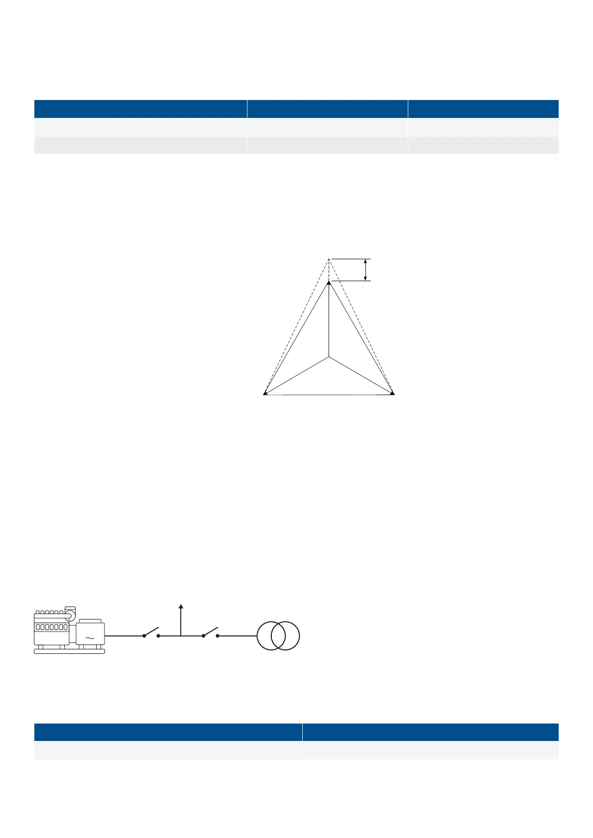
As indicated in the vector diagram, there is a difference in voltage values at an error situation for the phase-neutral voltage and the
phase-phase voltage.
The table shows the actual measurements at a 10 % under-voltage situation in a 400/230 volt system.
Phase-neutral Phase-phase
Nominal voltage 400/230 400/230
Voltage, 10 % error 380/207 360/185
The alarm will occur at two different voltage levels, even though the alarm set point is 10 % in both cases.
Example
The following 400 V AC system shows that the phase-neutral voltage must change 20 %, when the phase-phase voltage changes
40 volts (10 %).
Example:
U
NOM
= 400/230 V AC
Error situation:
U
L1L2
= 360 V AC
U
L3L1
= 360 V AC
U
L1-N
= 185 V AC
ΔU
PH-N
= 20 %
U
L3-L1
U
L1-N
U
L1-L2
U
L2-L3
U
L
2
-
N
U
L
3
-
N
20%
3.2 Phase sequence error and phase rotation
The AGCs is able to monitor the rotation of the voltage, and to give an alarm if the voltage is rotating in the wrong direction. The
AGC can monitor the rotation in both direction. From the alarm it is possible to set different failclasses, which give different
possibilities. The documentation about phase sequence error can divided into two sections, where the first chapter will be about
Single DG applications, and the other chapter will be about standard/multiple controller applications.
3.2.1 Single DG applications
A single DG application is able to handle up to one genset, one generator breaker and one mains breaker. An application like this is
shown below:
When the AGC is mounted correctly, the gensets voltage measurements are mounted between the Generator Breaker (GB) and the
genset. The other voltage measurements are mounted between the Mains Breaker (MB) and the incoming grid connection. On the
different controllers the voltage terminals is shown below:
Genset voltage terminals
Mains voltage terminals
79-84 85-89
DESIGNER'S HANDBOOK 4189341275A EN Page 65 of 196

 Loading...


