Multi-line 2
Application 1:
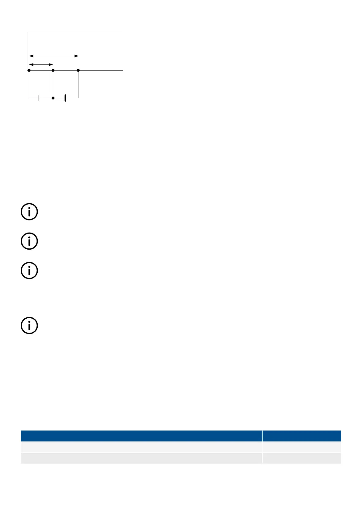
Start/Manoeuvre
battery
AUX
- +
A E B
- +
MI 1
The power supply measurement is used as the reference RF1 (points A and B) in menu 6432 and multi-input 1 is used as the type
T1 (points A and E) in menu 6431. By making these measurements, it is possible to calculate the voltage between E and B. This
gives a full picture of battery voltages, for example:
• Measured value A/B (RF1) = 21 V DC
• Measured value A/E (T1) = 12 V DC
• Calculated value E/B (RF1 – T1) = 9 V DC
• Battery asymmetry = E/B – (RF1*1/2) = 9 – (21*1/2) = -1.5 V DC
INFO
If application 3, 6 or 7 is used, it is expected that one of the multi-inputs is used for the battery test of the starter battery.
INFO
It is expected that the multi-inputs used for the battery asymmetry are configured to "0 to 40 V DC".
INFO
The selection power supply is referring to the supply on terminals 1 and 2.
Battery asymmetry alarm
Alarms for battery asymmetry 1 and 2 are set up in menus 6440 and 6450.
INFO
The set point in menus 6440 and 6450 is only set in positive values, however, it will also trigger if the battery asymmetry
calculation results in a negative value.
6.35 Internal battery
6.35.1 Memory backup
When changing the internal battery for the memory, all settings will be lost. The memory backup feature gives the possibility to back
up the controller settings, and after replacing the battery the settings can be restored.
DEIF recommends that a backup is made at least when the commissioning is tested and done. The following settings will be stored
in the backup:
Type
Stored
Identifiers X
Counters X
DESIGNER'S HANDBOOK 4189341275A EN Page 157 of 196

 Loading...


