EasyManuals Logo

Delta AS Series User Manual

Delta AS Series
662 pages
To Next Page IconTo Next Page
To Previous Page IconTo Previous Page
Page #224 background imageLoading...
Page #224 background image
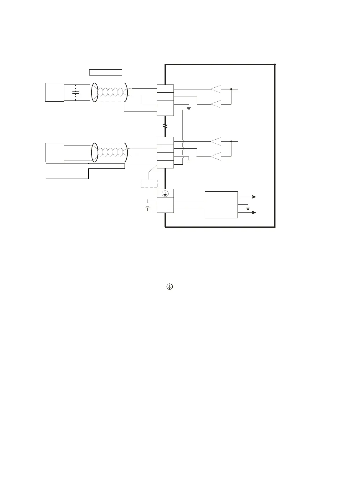
4.9.4 Wiring AS04DA-A
Con verte r
VO4
IO4
AG
CHX
0mA~20mA
CH4
AG
VO1
IO1
AG
CHX
-10V~+10V
*2
CH1
AG
24VDC
DC/DC
+15V
-15V
AG
SLD
SLD
FE
*3
0V
24V
*4
*4
AC motor drive,
recorder,
proportioning v alve
AC motor drive,
recorder,
proportioni ng valve
Shielded cable*1
Shielded c able*1
Voltage output
Current output
*1. Use shielded cables to isolate the analog input signal cable from other power cables.
*2. If noise in the input voltage results in noise interference in the wiring, connect the module to a capacitor with
a capacitance between 0.10.47 μF with a working voltage of 25 V.
*3. Connect the SLD to FE. Connect FE and the terminal to ground.
*4. Every channel can work with the wiring shown above.
Send Quote Requests to info@automatedpt.com
Call +1(800)985-6929 To Order or Order Online At Deltaacdrives.com
Send Quote Requests to info@automatedpt.com
Call +1(800)985-6929 To Order or Order Online At Deltaacdrives.com

Table of Contents

Other manuals for Delta AS Series

Questions and Answers:

Question and Answer IconNeed help?

Do you have a question about the Delta AS Series and is the answer not in the manual?

Delta AS Series Specifications

General IconGeneral
SeriesAS Series
Power Supply24VDC
Cooling MethodNatural convection
Programming LanguageFunction Block Diagram (FBD)
Communication InterfaceEthernet, RS-232, RS-485
Output Voltage24V DC
Output Current2A
Operating Temperature55°C
Storage Temperature70°C
Protection FeaturesOvervoltage
CertificationsCE, UL

Related product manuals