Users can select RTU1 Enable to enable this RTU function. Each RTU can be set individually.
Users can set a station address and IP address.
Users can set RX mapping address and RX mapping length to make the digital input points of DI module
connected to RTU mapped to X/M devices and length of PLC CPU. While, the RY mapping address and length
set is used for making the digital output points of DO module mapped to Y/M devices and length of PLC CPU.
Users can set RCR Read mapping address and RCR Read mapping length to make the analog input points of
AI module connected to RTU mapped to D/SR devices and length of PLC CPU. While, the RCR Write mapping
address and length set is used for making the analog output points of AO module mapped to D/SR devices and
length of PLC CPU.
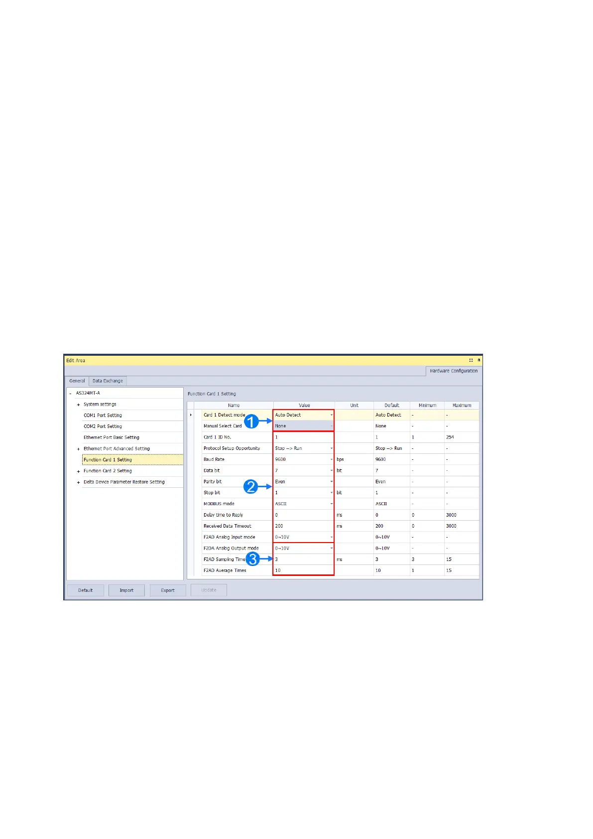
8.2.14 Function Card 1 Setting
The
Function Card 1 Setting
table is used for setting parameters of function card in AS300 series CPU module, which
is installed by inserting to the slot. For AS100 and AS200 Series PLC CPU, there is no Function Card 1 and thus there
is no settings for Function Card 1.
Users can select
Auto
in
Card1 Detect mode
box to detect the actual card model and setting
or
Manual
to
select the AS--F232/ F422/ F485/F2AD/F2DA function card which need be configured in the
Manual Select
Card
box.
For the setting of parameters in AS--F232/ F422/ F485.
Users can set
F2AD
to receive the signal of 0~10V or 4~20mA in
F2AD Analog Input Mode
box and set F2AD
to send the signal of 0~10V or 4~20mA in
F2DA Analog Output Mode
box. The average times are set in
F2AD
Sampling Time
and
Average Times
boxes respectively.
Send Quote Requests to info@automatedpt.com
Call +1(800)985-6929 To Order or Order Online At Deltaacdrives.com
Send Quote Requests to info@automatedpt.com
Call +1(800)985-6929 To Order or Order Online At Deltaacdrives.com
 Loading...
