2.7.2 Counting Module Profiles
2
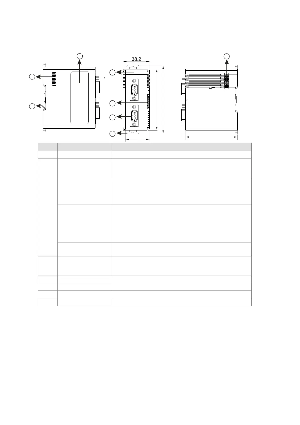
POWER LED indicator
(Blue)
Indicates the status of the power supply
ON: the power is on
Error LED indicator
(Red)
Error status of the module
ON: a serious error occurs in the module.
OFF: the module is normal.
Blinking: a minor error occurs in the module.
Counter LED indicator
for Ch1 Act. & Ch2 Act.
(Green)
Counting status of the module
OFF: the counter is disabled.
ON: the counter is enabled but the result of counting is not changed.
Blinking: the result of counting is updating.
When SSI input:
Blinking: the counter is enabled and the position value is updating.
Input / output LED
ON: Receives an input / output signal
OFF: Receives no input / output signal
3 D-sub 15
Input: connected for pulse input and encoder
Output: connected to loads to be driven
Power: providing external encoder +5 VDC
Secures the module onto the DIN rail
Connects the modules
On the DIN reail for grounding
Nameplate
Send Quote Requests to info@automatedpt.com
Call +1(800)985-6929 To Order or Order Online At Deltaacdrives.com
Send Quote Requests to info@automatedpt.com
Call +1(800)985-6929 To Order or Order Online At Deltaacdrives.com
 Loading...
