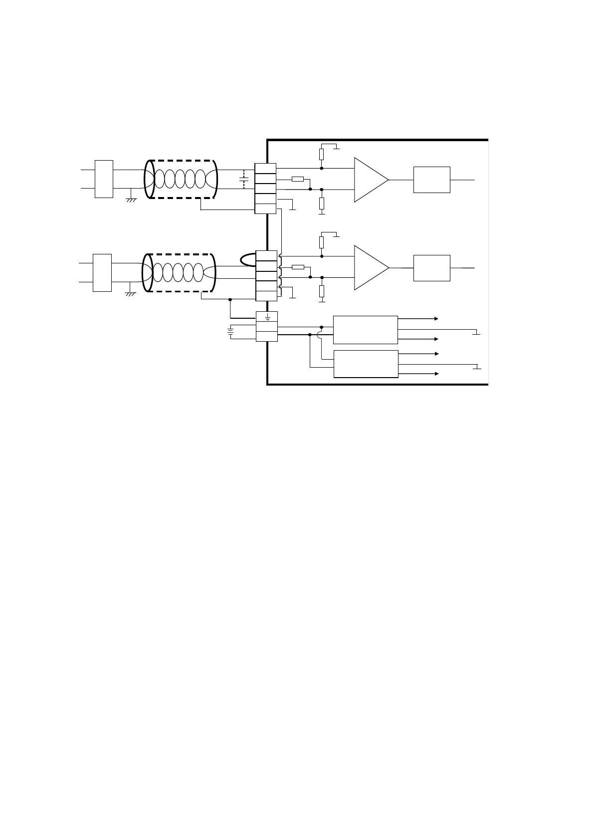
4.9.6.2 Analog Input Wiring
• 4-wired
+24V
0V
-
10V~+10V
+
-
AG1
AG1
1MΩ
AG1
1MΩ
INA1 ADC1
CH1
25 0Ω
Current input
+24V
0V
-
20mA~+20mA
+
-
Shielded cable *1
AG2
AG2
1MΩ
AG2
1MΩ
INA2 ADC2
CH2
250 Ω
24V
0V
DC/DC
Converter 1
DC/DC
Converter 2
+15V
-15V
AG1
+15V
-15V
AG2
CHX
CHX
*3
*2
*4
*4
*5
*5
V2+
I2+
VI2-
AG2
SLD
V1+
I1+
VI1-
AG1
SLD
Shielded cable *1
Voltage input
*1. Use shielded cables to isolate the analog input signal cable from other power cables.
*2. If the module is connected to a current signal, the terminals Vn and In+ (n=1–2) must be short-circuited.
*3. If variability in the input voltage results in interference within the wiring, connect the module to a capacitor
with a capacitance between 0.1–0.47 μF and a working voltage of 25 V.
*4. The wording “CHX” indicates that very channel can operate with the wiring presented above.
*5. If the environment is severe or there is interferences in 24 V pwer supply, short-circuit AGn (n=1-2) and the
input signal.
Send Quote Requests to info@automatedpt.com
Call +1(800)985-6929 To Order or Order Online At Deltaacdrives.com
Send Quote Requests to info@automatedpt.com
Call +1(800)985-6929 To Order or Order Online At Deltaacdrives.com
 Loading...
