AX-Series Motion Controller Instructions Manual Chapter 2
247
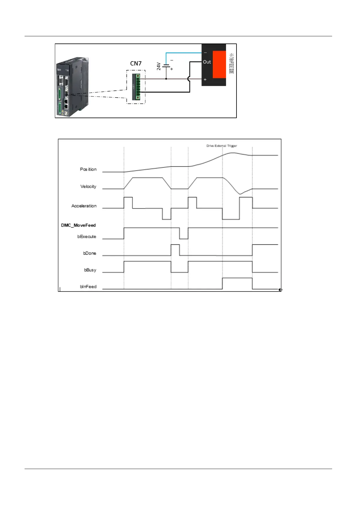
Timing Diagram
1. After DMC_MoveFeed has started, the axis starts to run with parameters such as target position, velocity,
acceleration and motion mode input in the Function block, and waits for the Trigger signal in the controller
mode.
2. Since the first segment of the target movement uses the relative mode (RELATIVE), and the error detection
selection (ErrorDetect) is False, when the target position is reached, the DMC_MoveFeed operation is
completed, and bDone turns to True.
3. Restart DMC_MoveFeed, and trigger the external signal of the driver when the first segment of target
movement has not been completed.
4. After triggering, the axis will follow the position and speed of the second standard movement. Since the
standard distance (lrFeedDistance) is negative, the axis will run in the opposite direction after triggering.
5. The trigger position of the drive mode can be obtained by querying the Touch probe pos1 pos value (60BAh).
Since the Drive trigger is more real-time than the controller, there will be a slight error in observing the
relationship between the InFeed and the position.
 Loading...

