AX-Series Motion Controller Instructions Manual Chapter 2
367
and it is zero at the middle point. So the Jerk is infinite at the start position and end position, which
is prone to shock and vibration. So the curve type is suitable for applications in the medium and
Acceleration sine curve
Used in the situation where the follower needs to perform a cycloid motion.
This curve is a sine curve in the acceleration diagram, and the acceleration at the start position
and the end position is zero, so the jump produced will not cause the acceleration to reach infinity.
And thus the curve type can be applied for high-speed operation due to smooth operation.
Modified acceleration
The acceleration graph of the curve is a sine curve changed from a typical ladder graph, so that
the acceleration is smoother. The curve type is applied for high-speed operation.
Modified acceleration
trapezoidal curve
The acceleration graph of the curve is a sine curve changed from oblique straight lines for the
acceleration and deceleration segments of a typical ladder diagram. So the acceleration has better
smoothness. The curve type is applied for high-speed operation.
Cubic spline curve
The acceleration at the start and end points of the cubic curve is zero. That is, there is no force on
both ends of the follower.
Cubic spline curve
(clamp boundary)
The velocities for the start and end points of the cubic curve are user-set values. The acceleration
rates for both ends are the positive maximum and negative maximum, so shock and vibration are
Cubic spline curve
The cubic curve is used when four or more key points are used as interpolation points in order to
link two boundary curves as well as avoid the Runge phenomenon of multi-order curves.
Troubleshooting
When an error occurs during the execution of the instruction or the axis enters “Errorstop” state, bError changes to True
and the axis stops running. To confirm current error state, see the error code in ErrorID.
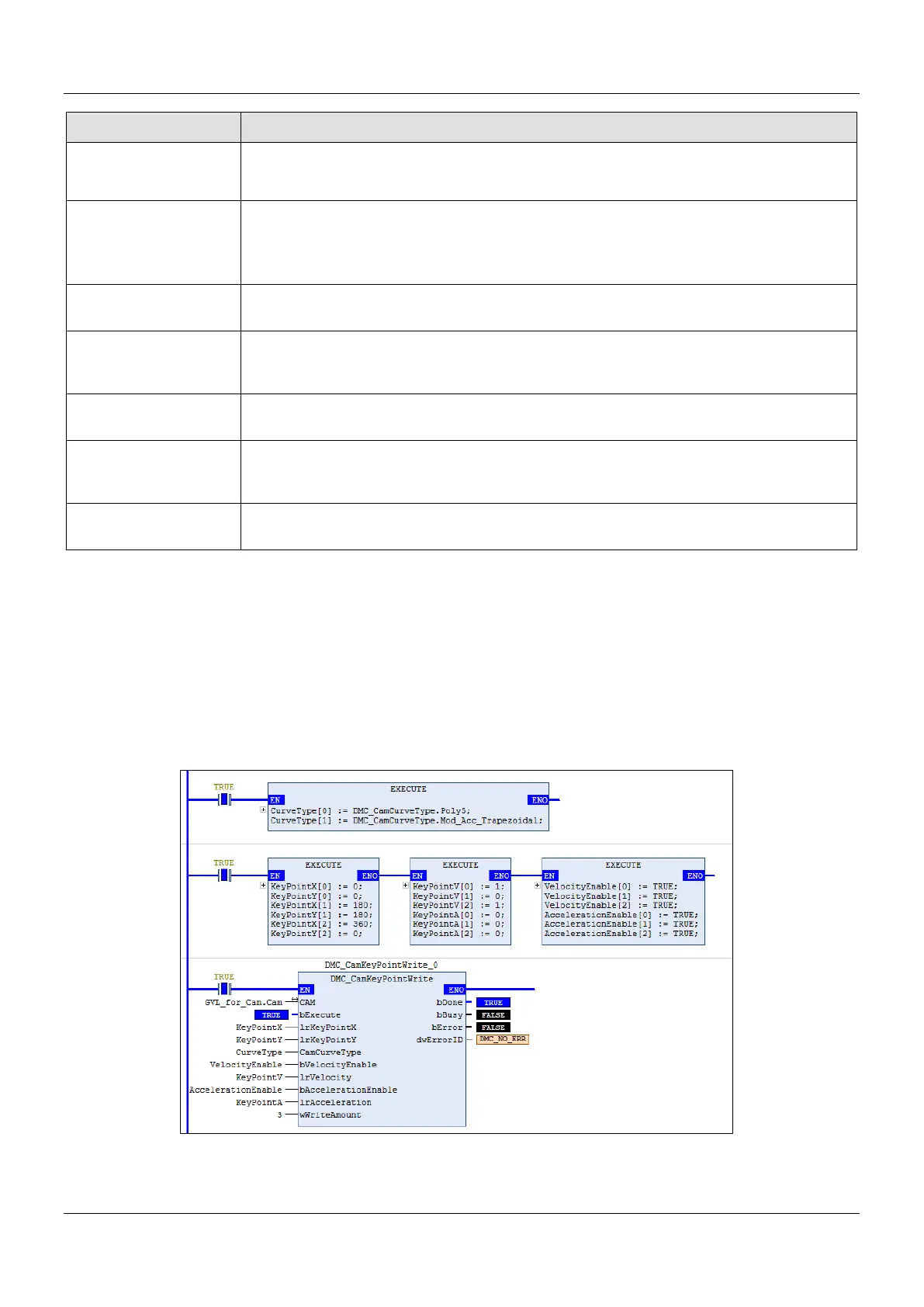
Programming Example
Programming Example1:
The example illustrates the synchronized motion based on the cam table generated from DMC_
DMC_CamKeyPointWrite.
The cam table generated from DMC_CamKeyPointWrite can be used by MC_CamTableSelect directly.
 Loading...

