AX-Series Motion Controller Instructions Manual Appendix A
530
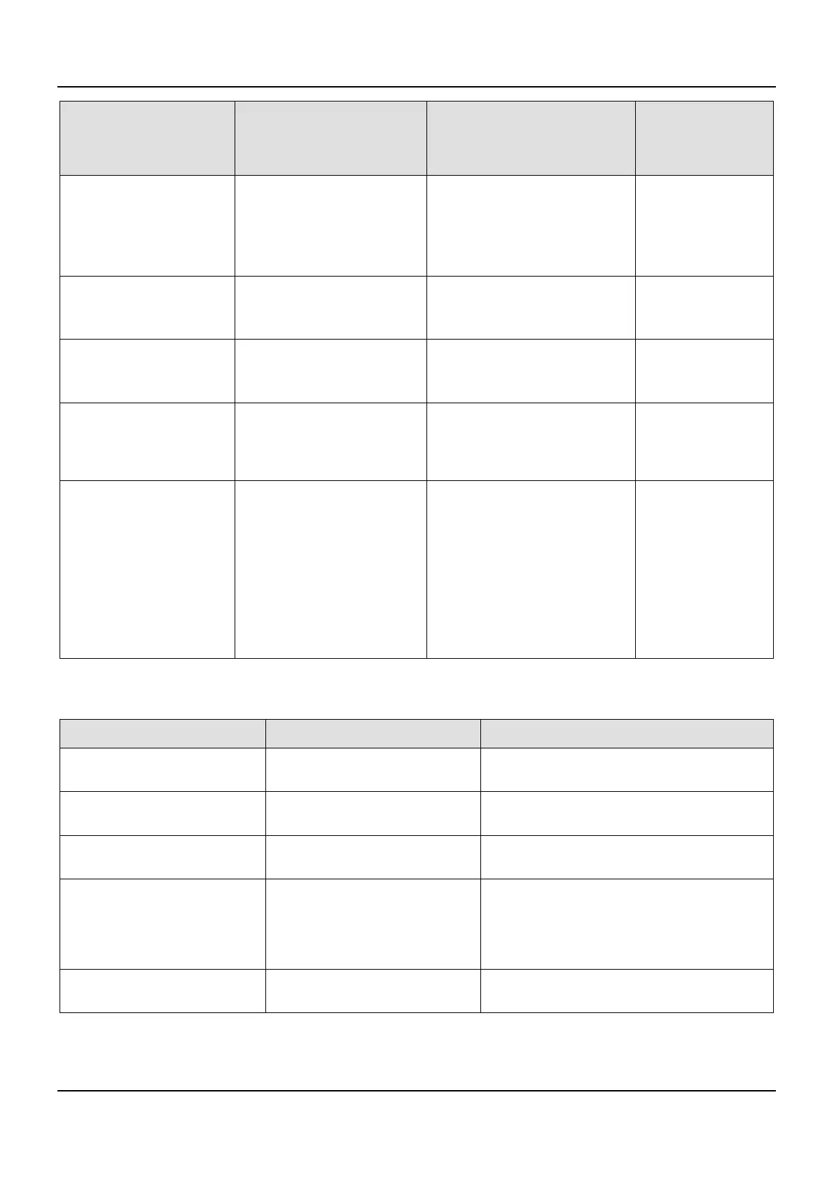
Data Type Value Description
Applicable Function
Block
Instruction and its
MC_DIRECTION -1: negative
0: shortest
1: positive
2: current
-1: reverse rotation
0: shortest path
1: Forward rotation
2: current direction
function block:
DMC_MoveFeed
Pin: Direction
DMC_MOVEMODE 0: ABSOLUTE
1: RELATIVE
2: VELOCITY
0: absolute mode
1: Relative mode
2: Speed Mode
function block:
DMC_MoveFeed
Pin: MoveMode
DMC_LINKOPTION 0: COMMANDEEXECUTION
1: TRIGGERDETECTION
0: start immediately
1: Drive side startup
2: Set the spindle position to start
function block:
DMC_MoveMoveLink
DMC_STARTDISTANCEMO
DE
0: ABSOLUTE
1: RELATIVE
0: absolute mode
1: Relative mode
function block:
DMC_MoveMoveLink
Pin:
StartDistanceMode
DMC_COORD_SYSTEM 0: ACS
1: MCS
2: WCS(Reserved)
3: PCS_1(Reserved)
4: PCS_2(Reserved)
5: TCS(Reserved)
0: Motion axis coordinates
1: Mechanical coordinates
2: world coordinates (reserved)
3: Workpiece coordinate 1
(reserved)
4: Workpiece coordinate 2
(reserved)
5: Tool coordinates (reserved)
function block:
DMC_MoveDirectAbs
olute
DMC_MoveDirectRel
ative
DMC_GroupReadSet
Position
DMC_GroupReadSet
Position
Pin: CoordSystem
The Data Types listed below are Structure type:
AXIS_REF_SM3
*
Applied to MC_ / DMC_ function
This structure contains all the required data and
parameters for axis motion.
DMC_AXIS_GROUP_REF
*
Applied to DMC_Group function
This structure contains all the required data and
parameters for group motion.
AXIS_REF_VIRTUAL_SM3
Applied to MC_ / DMC_ function
This structure contains all the required data and
parameters for virtual axis motion.
TRIGGER_REF
MC_TouchProbe
MC_AbortTrigger
Includes the trigger information
The specified trigger channel
The trigger condition and the mode (Triggered
on the rising or falling edge of the trigger
signal.)
MC_CAM_REF MC_CamTableSelect
This structure contains information of the CAM
table and points.
*Note: refer to AX-3 Series operational manual for more details of structural type parameters.

 Loading...


