85
6.3 I/O and AC Input Wiring
6.3.1 Multi-core Cables with Connectors
Multi-core cables with connectors to be used for the I/O wiring of the Robot Controller
are options. Select an appropriate cable from the table given below if necessary.
I/O Cables (Options)
No. Name Part Number Remarks
1 Standard I/O cable set (8m) 410149-0940 Including Nos. 1-1 and 1-2
1-1 Mini I/O cable set (8m) 410141-2700 Connector set: 410159-0190
1-2 Hand I/O cable set (8m) 410141-1740
2 Standard I/O cable set (15m) 410149-0950 Including Nos. 2-1 and 2-2
2-1 Mini I/O cable set (15m) 410141-2710 Connector set: 410159-0190
2-2 Hand I/O cable set (15m) 410141-1750
If you do not use optional cables listed above, use the recommended connectors and
cables listed below.
Recommended Connectors for I/O Cables and Cable Standards
Connector
name
Connector
model/manufacturer
Cable Standards Remarks
Mini I/O
PCR-E68FS connector
PCS-E68LPA-1E cover
(HONDA TSUSHIN
KOGYO Co., LTD)
UL2789 - With shield
Equivalent to AWG28x34P
HAND I/O
PCR-E20FS connector
PCS-E20LA cover
(HONDA TSUSHIN
KOGYO Co., LTD)
UL2789 - With shield
Equivalent to AWG28x20P
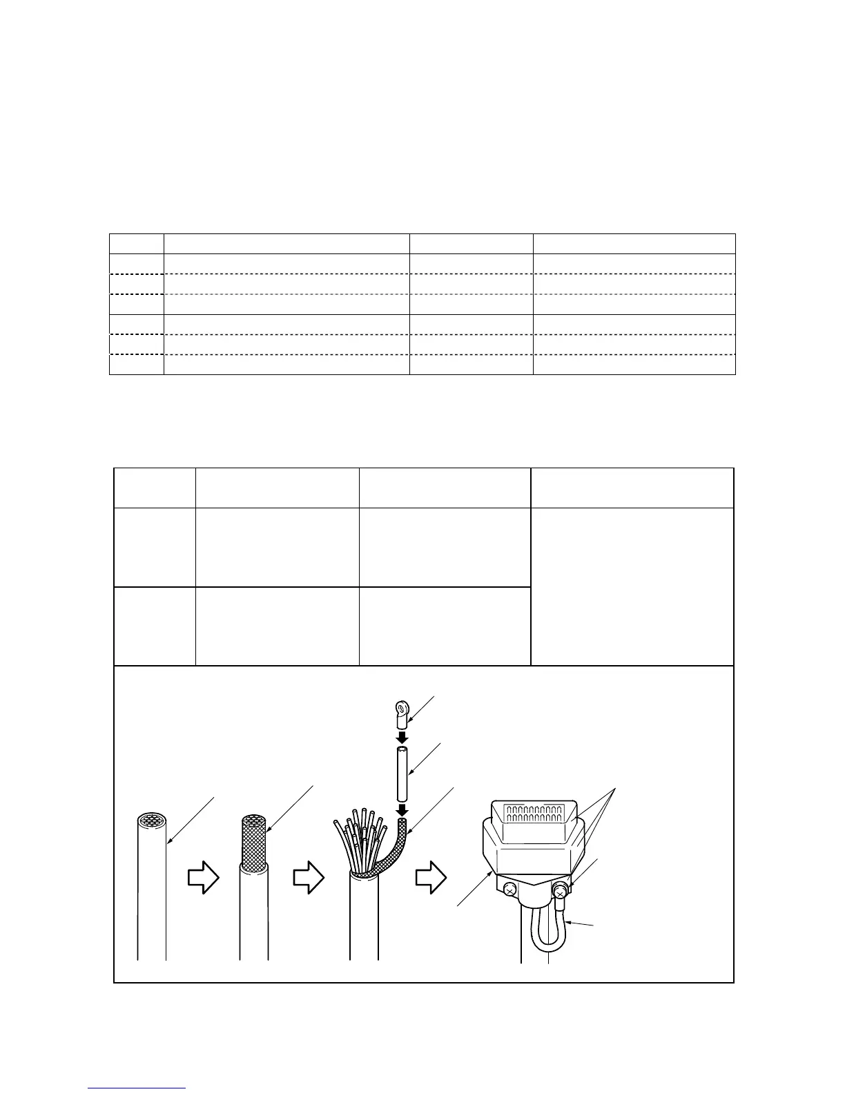
Caution: Be sure to modify the
shielding wire at the end of the
cable to be used, as shown
below. Without this modification,
the robot may malfunction due to
noise.
I/O cable
Braided
shielding wire
The connector shell
should be made of
conductive metal.
Crimp terminal
Vinyl tube
Shielding wire
I/O power
connector
Fasten to the connecto