132
8.2 I/O Allocation in Individual Allocation Modes
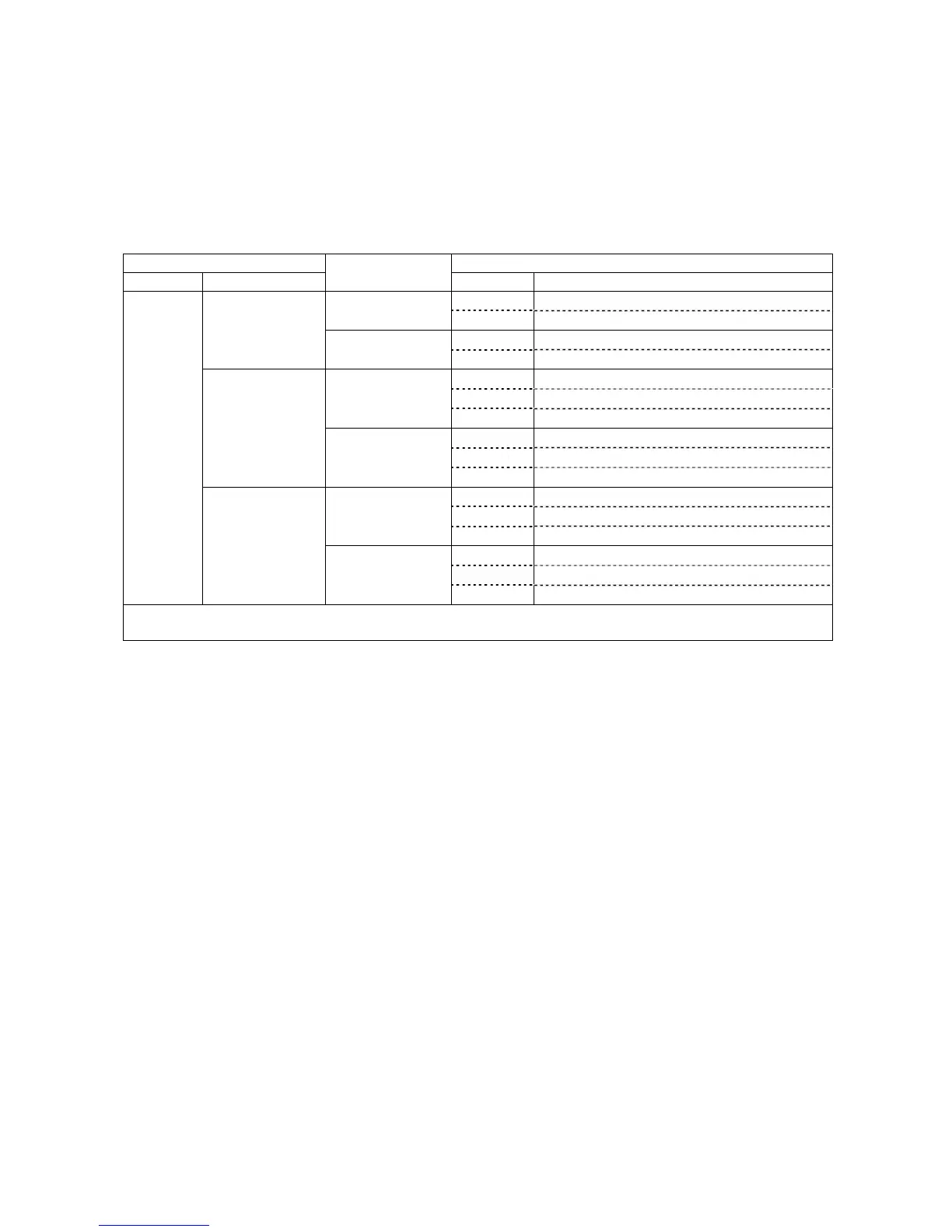
The table below lists the I/O allocation for extension boards in individual
allocation modes. For details, refer to Section 8.5 "I/O Allocation Tables for
Individual Allocation Modes."
Note: For the I/O allocation for the DeviceNet master/slave board, see the
allocation tables for the DeviceNet master and slave boards.
I/O Allocation of Extension Boards in Individual Allocation Modes
I/O extension boards
Allocation for CN8, CN10, and extension boards
Extension 1 Extension 2
Allocation modes
I/O Allocation tables to apply
CN8 INPUT (CN8) in I/O-box compatible mode
I/O-box compatible
mode
CN10 OUTPUT (CN10) in I/O-box compatible mode
CN8 INPUT (CN8) in I/O-box standard mode
–
I/O-box standard
mode
CN10 OUTPUT (CN10) in I/O-box standard mode
CN8 INPUT (CN8) in I/O-box all user I/O mode
CN10 OUTPUT (CN10) in I/O-box all user I/O mode
I/O-box compatible
mode
Extension 2 Extension boards in I/O-box compatible mode
CN8 INPUT (CN8) in I/O-box all user I/O mode
CN10 OUTPUT (CN10) in I/O-box all user I/O mode
DeviceNet slave
board
CC-Link board
PROFIBUS-DP
slave board
I/O-box standard
mode
Extension 2 Extension boards in I/O-box standard mode
CN8 INPUT (CN8) in I/O-box compatible mode
CN10 OUTPUT (CN10) in I/O-box compatible mode
I/O-box compatible
mode
Extension 2 Extension boards in I/O-box all user I/O mode
CN8 INPUT (CN8) in I/O-box standard mode
CN10 OUTPUT (CN10) in I/O-box standard mode
Parallel
I/O board
Parallel I/O board
DeviceNet master
board
S-LINK V board
I/O-box standard
mode
Extension 2 Extension boards in I/O-box all user I/O mode
Note: Extensions 1 and 2 correspond to the ones listed in the "Allocation Mode Available with the I/O Conversion Box"
table on the previous page.
8.3 Notes on Using the I/O Conversion Box
(1) Parameter change for switching between allocation modes
To switch to the I/O-box compatible or standard mode, you need to change
parameters using the teach pendant or WINCAPSII. For the changing procedure,
refer to the RC7M Controller OPTIONS MANUAL, Section 4.6.
(2) Power supply setting for mini I/O board (CN5) or parallel I/O board
To use the I/O conversion box, select 24 V power supply (internal or external) on
I/O POWER (CN7). You also need to set up the power supply for the mini I/O board
and parallel I/O board to match the power supply setting on I/O POWER (CN7).
The factory default is external power supply.
For details about the mini I/O board, see Section 4.2.1 or 5.2.1.
For details about the parallel I/O board, refer to the RC7M Controller OPTIONS
MANUAL, Section 5.2.2.