53
4.2 Robot Controller I/O Circuits (NPN type)
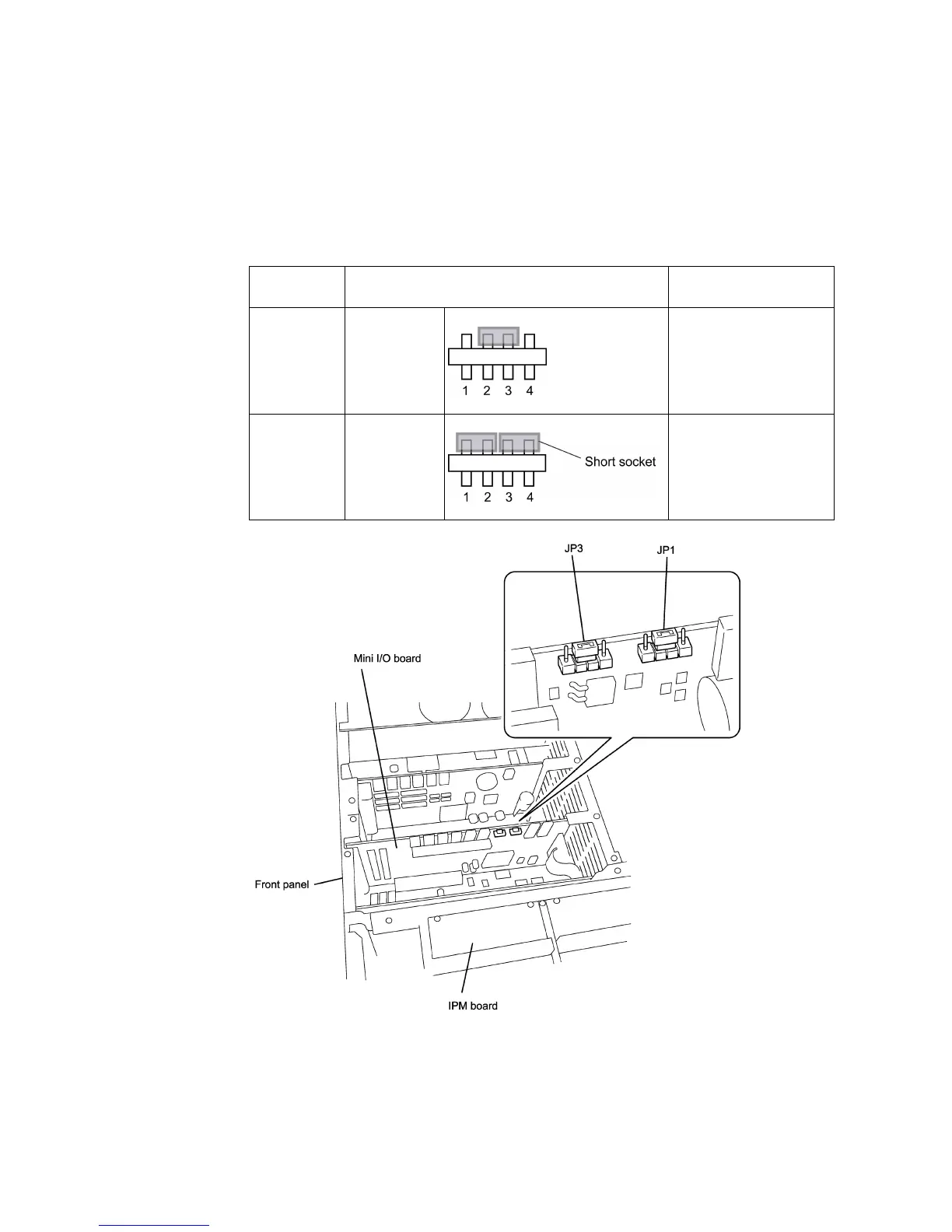
4.2.1 Setting up Mini I/O Power Supply
The power supply (+24 VDC) for the Mini I/O can be switched between internal and
external power sources by changing the jumper switch setting as listed below. The
factory default is external power source setting.
Power supply
for I/O
Jumper switches JP1 and JP3 on the
controller printed circuit board
Description
External
source
Short-circuit
pins 2 and 3
(factory
default)
Do not change the
factory default setting.
Internal
source
Short-circuit
pins 1 and 2,
and pins 3
and 4
Remove the controller
top cover and change
the JP1 and JP3
settings with short
sockets that come with
the robot.
Note: Switching the power supply setting for I/O from external to internal changes the
assignment to terminals #32 to #34 and #66 to #68 on CN5 from external DC power input to
internal DC power output. For details, refer to the circuit configuration examples in Sections
4.2.2 and 4.2.3.