69
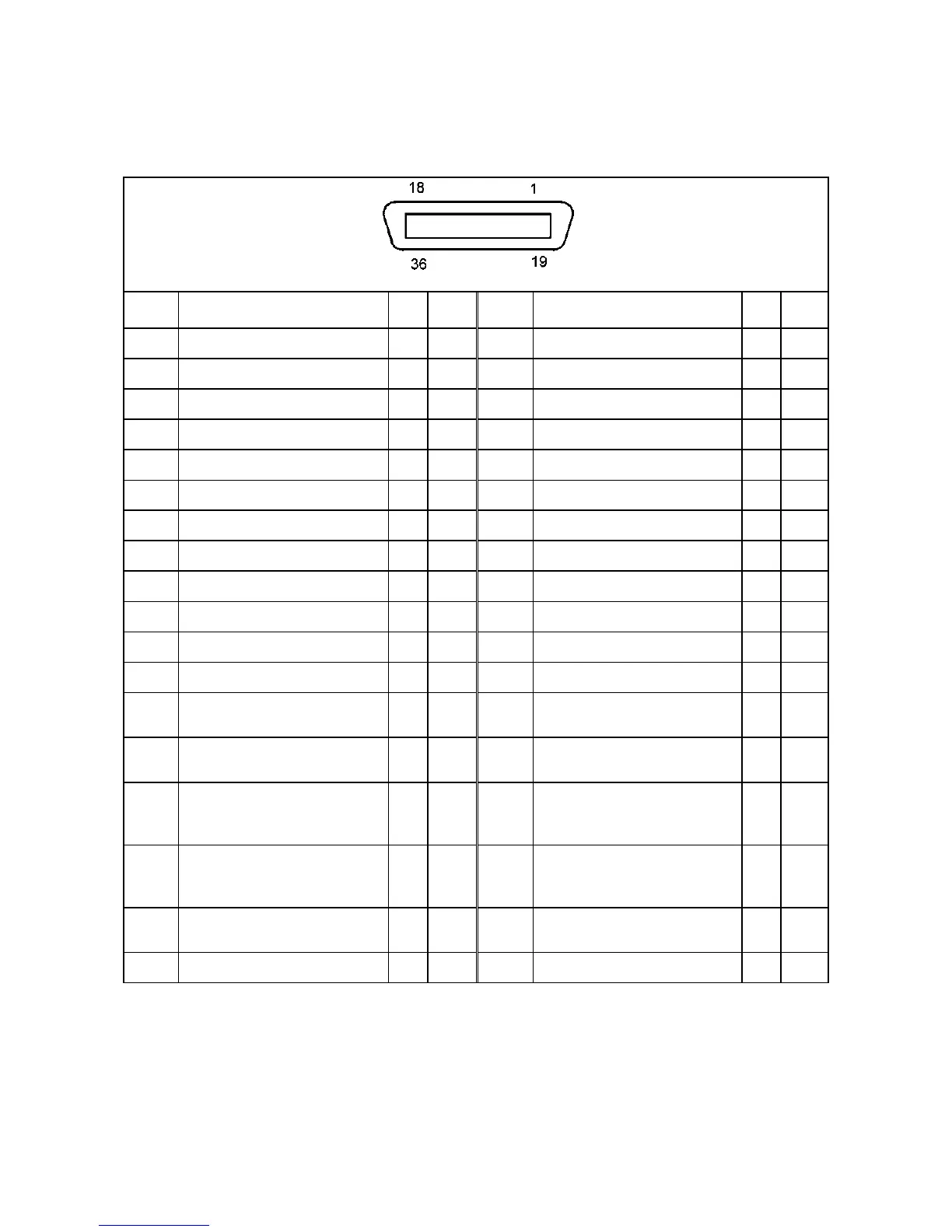
5.1.4 Safety I/O (CN10):System-I/O connecter (Global type of controller)
Safety I/O (CN10) Pin Assignment
View from the cable side
Terminal
No.
Signal name
Port
No.
Wire
color
Terminal
No.
Signal name
Port
No.
Wire
color
1 External Emergency Stop 1, b-1 (input)
Black 19 External Emergency Stop 1, b-2 (input)
Pink
2 External Emergency Stop 2, b-1 (input)
Brown 20 External Emergency Stop 2, b-2 (input)
Pink
3 Reserved.
Red 21 Reserved.
Pink
4 Reserved.
Orange 22 Reserved.
Pink
5 Protective Stop 1, -1 (input)
Yellow 23 Protective Stop 1, -2 (input)
Pink
6 Protective Stop 2, -1 (input)
Green 24 Protective Stop 2, -2 (input)
Pink
7 Enable Auto 1, -1 (input)
Blue 25 Enable Auto 1, -2 (input)
Pink
8 Enable Auto 2, -1 (input)
Black 26 Enable Auto 2, -2 (input)
Gray
9 ⎯
Brown 27 ―
Gray
10 Reserved.
Red 28 Reserved.
Gray
11 Reserved.
Orange 29 Reserved.
Gray
12 Reserved.
Yellow 30 Reserved.
Gray
13
Pendant Emergency Stop 1, b-1
(output)
Green 31
Pendant Emergency Stop 1, b-2
(output)
Gray
14
Pendant Emergency Stop 2, b-1
(output)
Blue 32
Pendant Emergency Stop 2, b-2
(output)
Gray
15
Deadman SW 1, -1 (output)
[Enable SW 1, -1]
(Safety relay)
Violet 33
Deadman SW 1, -2 (output)
[Enable SW 1, -2]
(Safety relay)
Gray
16
Deadman SW 2, -1 (output)
[Enable SW 2, -1]
(Safety relay)
Black 34
Deadman SW 2, -2 (output)
[Enable SW 2, -2]
(Safety relay)
White
17
Contactor Contact Monitor 1, -1
(output)
Brown 35
Contactor Contact Monitor 1, -2
(output)
White
18 Reserved.
Red 36 Reserved.
White
Note 1: The optional I/O cable for the above connector consists of twisted pair wires--pairs of #1 and #19, #2 and #20, #18 and #36.
Note 2: The reserved pins and output pins should be prevented from direct contact with other pins or conductive part. Direct contact could
result in a controller failure or damage.
Note 3: To use Pendant Emergency Stop output signals, be sure to supply 24 V to terminals #13 and #14.