131
Chapter 8 I/O Allocation for I/O Conversion
Box (only for standard type of
controller)
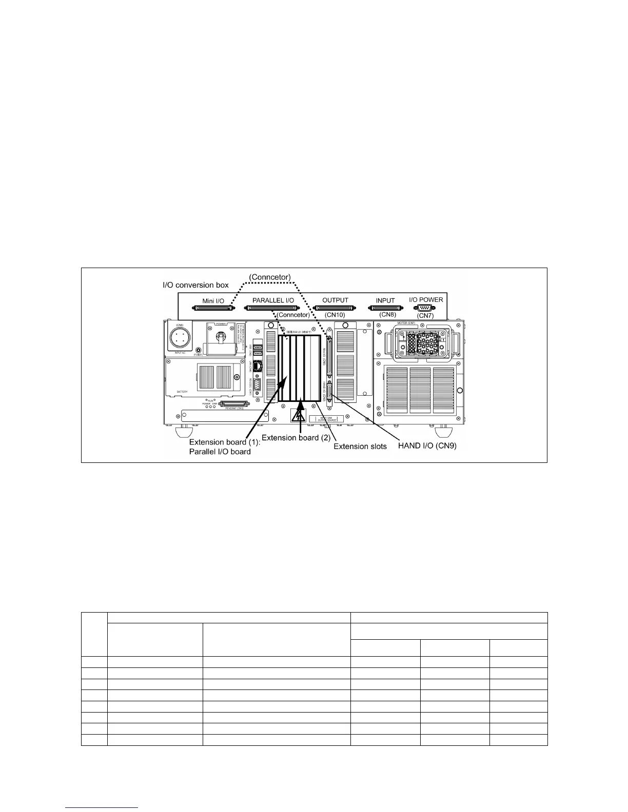
This chapter lists the I/O allocation tables to apply when the I/O conversion box is
mounted on the controller.
The I/O conversion box should be used with an optional parallel I/O board mounted so
that the "INPUT (CN8)," "OUTPUT (CN10)," and "I/O POWER (CN7)" used on the RC5
controller can be used as is.
Note: The I/O conversion box cannot be used for the global type of the controller.
For details about the I/O conversion box, refer to the RC7M Controller OPTIONS
MANUAL, Chapter 4, Section 4.7 "I/O Conversion Box."
8.1 I/O Allocation Modes with I/O Conversion Box Mounted
Using the I/O conversion box requires an optional parallel I/O board to be
mounted, for compatibility with the RC5 controller. The ports on the parallel I/O
board offset the shortage of standard mini I/O ports.
The table below lists the selectable allocation modes when the I/O conversion
box is used.
Allocation Mode Available with the I/O Conversion Box
I/O extension boards Allocation modes
I/O conversion box
No.
Extension 1 Extension 2
Compatible Standard All user I/O
1 Parallel I/O board –
√ √
2 Parallel I/O board Parallel I/O board
√ √
3 Parallel I/O board DeviceNet slave board
√ √
4 Parallel I/O board DeviceNet master board
√
5 Parallel I/O board DeviceNet master/slave board
√ √ √
6 Parallel I/O board CC-Link board
√ √
7 Parallel I/O board PROFIBUS-DP slave board
√ √
8 Parallel I/O board S-LINK V board
√ √ √