103
Chapter 7 I/O Allocation for I/O Extension
Board(s)
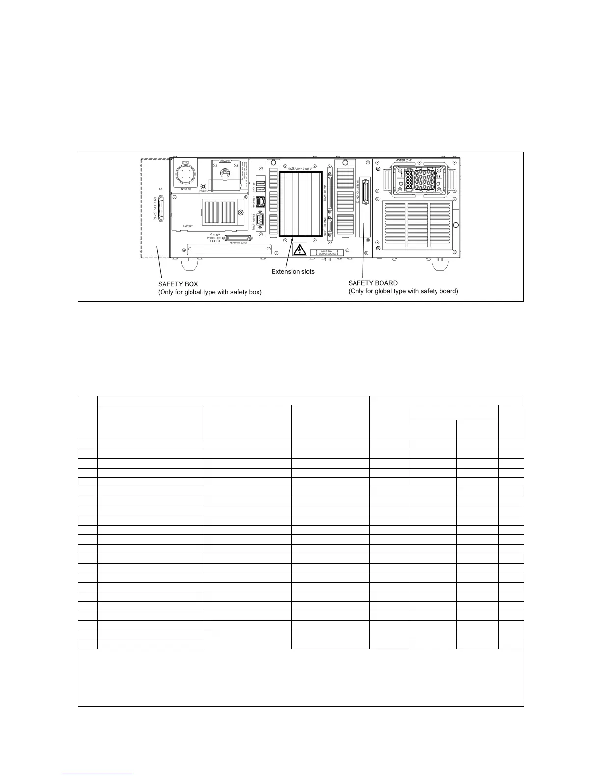
This chapter lists the I/O allocation tables to apply when I/O extension boards are
mounted on the controller. For details about I/O extension boards, refer to the RC7M
CONTROLLER OPTIONS MANUAL.
7.1 Combination of I/O Extension Boards and Allocation Modes
The table below lists the permitted combination of I/O extension boards and
selectable allocation modes.
Combination of I/O Extension Boards
I/O extension boards (Max. 2 boards) Allocation modes
Allocated to Extension 1
Combination
#
Extension 1 Extension 2 Extension 3
Mini I/O
dedicated
Compatible Standard
All
user
I/O
0 – – –
√
1 – S-LINK V board –
√
√
2 – DeviceNet master board –
√
3 – DeviceNet master board Parallel I/O board
√
4 – DeviceNet master board S-LINK V board
√
5 Parallel I/O board – –
√ √ √
6 Parallel I/O board Parallel I/O board –
√ √ √
7 Parallel I/O board S-LINK V board –
√ √ √ √
8 DeviceNet slave board – –
√ √
9 DeviceNet slave board Parallel I/O board –
√ √
10 DeviceNet slave board S-LINK V board –
√ √ √
11 DeviceNet master/slave board – –
√ √ √
12 DeviceNet master/slave board Parallel I/O board –
√ √ √
13 DeviceNet master/slave board S-LINK V board –
√ √ √
14 CC-Link board – –
√ √
15 CC-Link board Parallel I/O board –
√ √
16 CC-Link board DeviceNet master board –
√ √ √
17 CC-Link board S-LINK V board –
√ √ √
18 PROFIBUS-DP slave board – –
√ √
19 PROFIBUS-DP slave board Parallel I/O board –
√ √
20 PROFIBUS-DP slave board DeviceNet master board –
√ √ √
21 PROFIBUS-DP slave board S-LINK V board –
√ √ √
Note 1: Out of check-marked modes in the "Allocation modes" column, only one mode can be selected.
Note 2: Up to two I/O extension boards can be mounted on the controller. There are no restrictions on the choice of
extension slots or the mounting order.
Note 3: When two I/O extension boards are mounted, the controller recognizes the one inserted in the left-hand
extension slot as Extension 1. The allocation I/O port numbers on Extension 1 and 2 boards differ with each other.