104
7.2 I/O Allocation in Individual Allocation Modes
The table below lists the I/O allocation for extension boards in individual
allocation modes. For details, refer to Section 7.5 "I/O Allocation Tables for
Individual Allocation Modes."
Note: For the I/O allocation for the DeviceNet master/slave board, see the
allocation tables for the DeviceNet master and slave boards.
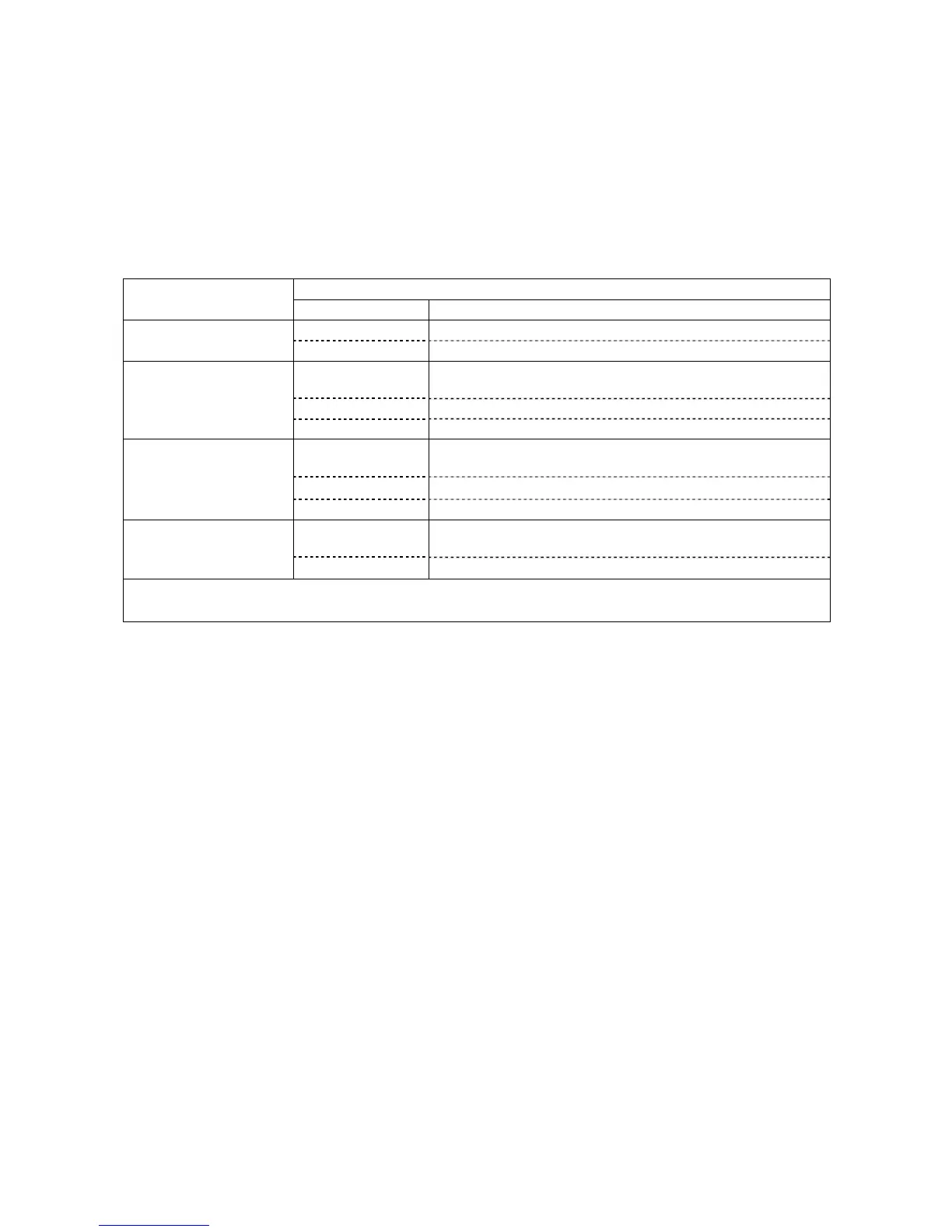
I/O Allocation of Extension Boards in Individual Allocation Modes
Allocation for CN5 and extension boards
Allocation modes
I/O Allocation tables to apply
CN5 Tables for mini I/O board in mini I/O dedicated mode
Mini I/O dedicated mode
Extensions 1, 2, 3 Tables for extension boards in all user I/O mode
CN5 Tables for mini I/O board in compatible, standard and all user
I/O modes
Extension 1 Tables for extension boards in compatible mode
Compatible mode
Extensions 2, 3 Tables for extension boards in all user I/O mode
CN5 Tables for mini I/O boards in compatible, standard and all
user I/O modes
Extension 1 Tables for extension boards in standard mode
Standard mode
Extensions 2, 3 Tables for extension boards in all user I/O mode
CN5 Tables for mini I/O board in compatible, standard and all user
I/O modes
All user I/O mode
Extensions 1, 2, 3 Tables for extension boards in all user I/O mode
Note: Extensions 1, 2, and 3 correspond to the ones listed in the "Combination of I/O Extension Boards" table on
the previous page.
7.3 Notes on Using I/O Extension Boards
(1) Parameter change for switching between allocation modes
To switch between the compatible, standard, and all user I/O modes, you need to
change parameters using the teach pendant or WINCAPSII. For the changing
procedure, refer to the RC7M Controller OPTIONS MANUAL, Section 4.6.
(2) Power supply setting for mini I/O board (CN5) or parallel I/O board
When using the mini I/O board (CN5) or parallel I/O board, you need to set up the
24 V power supply (internal or external). The factory default is external power
supply.
For details about the mini I/O board, see Section 4.2.1 or 5.2.1.
For details about the parallel I/O board, refer to the RC7M Controller OPTIONS
MANUAL, Section 5.2.2.