95
6.6 Replacing Fuses and Output ICs
6.6.1 Positions of Fuses and Output ICs
The robot controller is equipped with fuses to protect it from external wiring shorted.
If any fuse is blown, replace it according to the following procedure.
If an output signal error persists even after replacement of the output fuse, the related
output IC needs to be replaced.
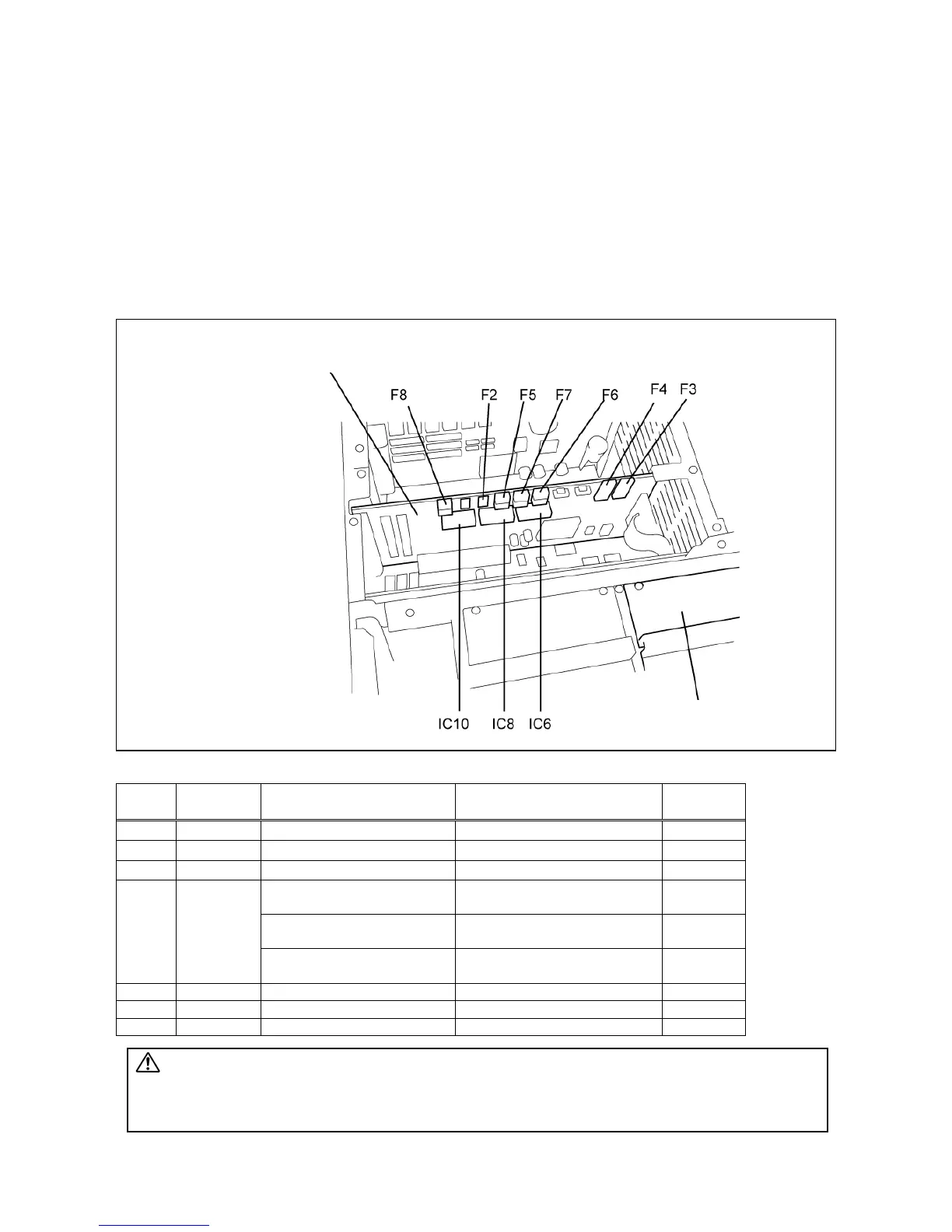
Fuses and output ICs are located in the robot controller as shown in the figure below.
Positions of Fuses (with the controller top cover removed)
Fuse Capacity
Corresponding output
connector and terminal No.
Signal name
I/O port
No.
F2 3.2 A Mini I/O, terminals 66 to 68
DC power input 0V (E0V)
---
F3 1.3 A Mini I/O, terminals 32 to 34
DC power input +24V(E24V)
---
F4 1.3 A Mini I/O, terminals 66 to 68
DC power input 0V (E0V)
---
Mini I/O, terminal 1
Power supply for Enable auto
(Internal +24V)
---
Mini I/O, terminal 2
External emergency stop 1b-1
(Internal +24V)
---
F5 1.3 A
Mini I/O, terminal 3
External emergency stop 2b-1
(Internal +24V)
---
F6 1.3 A Mini I/O, terminals 45 to 60 System output/User output 16 to 31
F7 1.3 A Hand I/O, terminals 1 to 8 Hand output 64 to 70
F8 1.3 A Hand I/O, terminal 17 Power supply for hand E24V ---
Caution F2 fuse is provided for protecting the circuitry from getting damaged if a voltage
of 30V or above is applied to the 24V external power source terminals. F2 fuse is
not mounted on a Mini I/O board in controllers whose product number is 02H018
or later (short-circuited instead).
Mini I/O board
IPM board
(Front panel side)