96
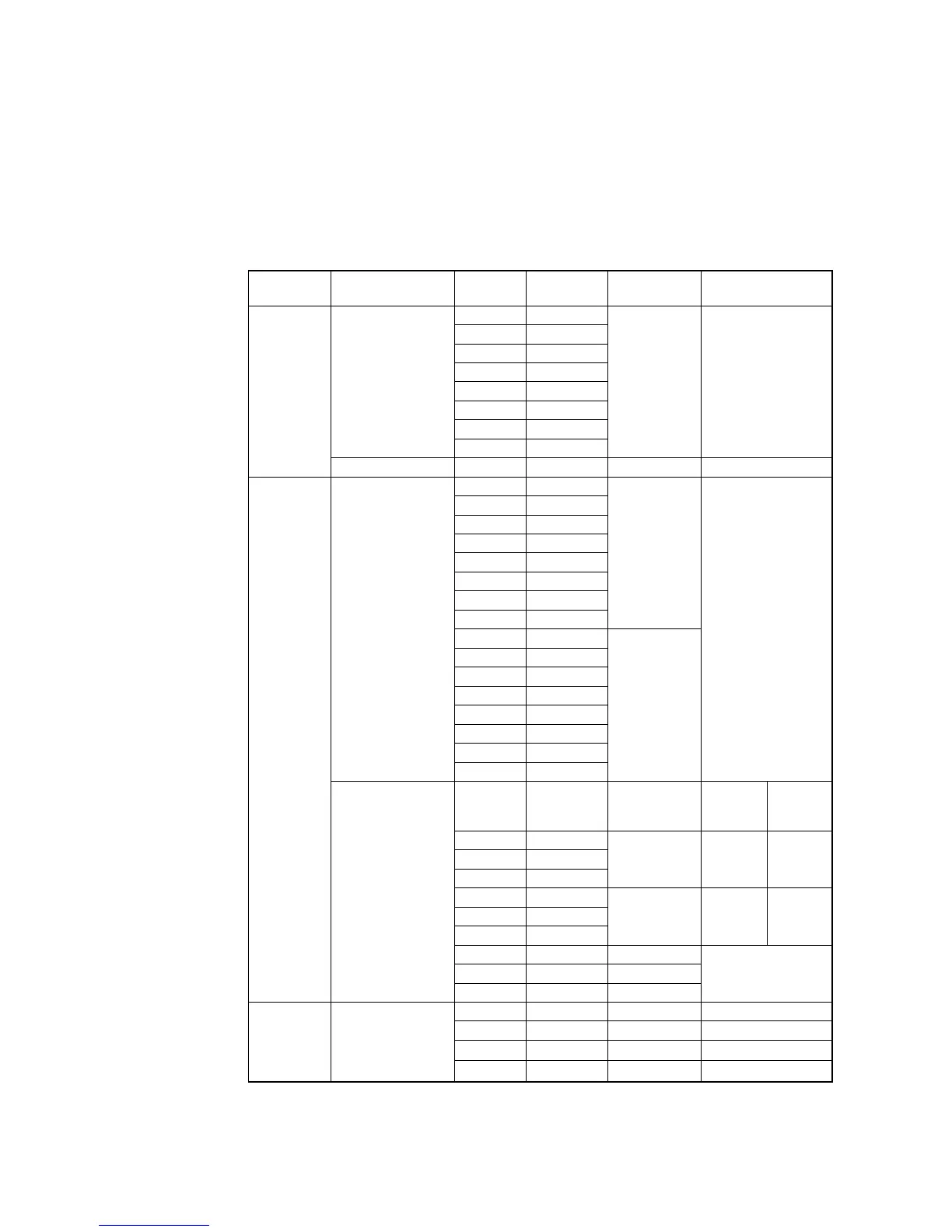
The table below lists the output ICs and fuses for the Mini I/O (CN5) and HAND I/O
(CN9). If an output signal error occurs, check the corresponding fuse.
Note: The Emergency Stop and Deadman output circuits use PolySwitches (resettable
fuses) that trip in an overcurrent condition to open the circuits. If a PolySwitch trips, turn
the power off and check the related circuit. (As long as the power is on, a PolySwitch
keeps tripping. After checking, therefore, turn the controller power off and on, then
check the circuit again.
Output ICs and Fuses
Connector
Name
Application Pin No. I/O Port No. Output IC Fuse
1 64
2 65
3 66
4 67
5 68
6 69
7 70
For output
8 71
IC10 F7 (1.3A)
HAND I/O
CN9
For power output 17, 18 – – F8 (1.3A)
45 16
46 17
47 18
48 19
49 20
50 21
51 22
52 23
IC6
53 24
54 25
55 26
56 27
57 28
58 29
59 30
For output
60 31
IC8
F6 (1.3A)
External
power
supply
Internal
power
supply
32 –
33 –
34 –
– –
F3
(1.3A)
66 –
67 –
68 –
– –
F4
(1.3A)
1, 35 – –
2, 36 – –
Mini I/O
CN5
For 24 VDC
3, 37 – –
F5
(1.3A)
6, 40 – – PS5 (0.15A)
7, 41 – – PS6 (0.15A)
8, 42 – – PS3 (0.15A)
Reference:
PolySwitch
on Mini I/O
(CN5)
Emergency stop
and Deadman
output
9, 43 – – PS4 (0.15A)