12
Chapter 2
General Information about the Interface
2.1 Types and General Information about I/O Signals
This section describes the I/O signals for the Robot Controller.
The I/O signals are grouped into user I/O signals and system I/O signals.
Note: For the interface to apply when an I/O extension board or I/O conversion box is
mounted, refer to Chapter 7 or 8 in this manual, respectively, and the OPTIONS
MANUAL.
2.1.1 Types of System I/O Signals (Standard type of controller)
Seven input points for command execution are used to direct program start and other
instructions as I/O commands.
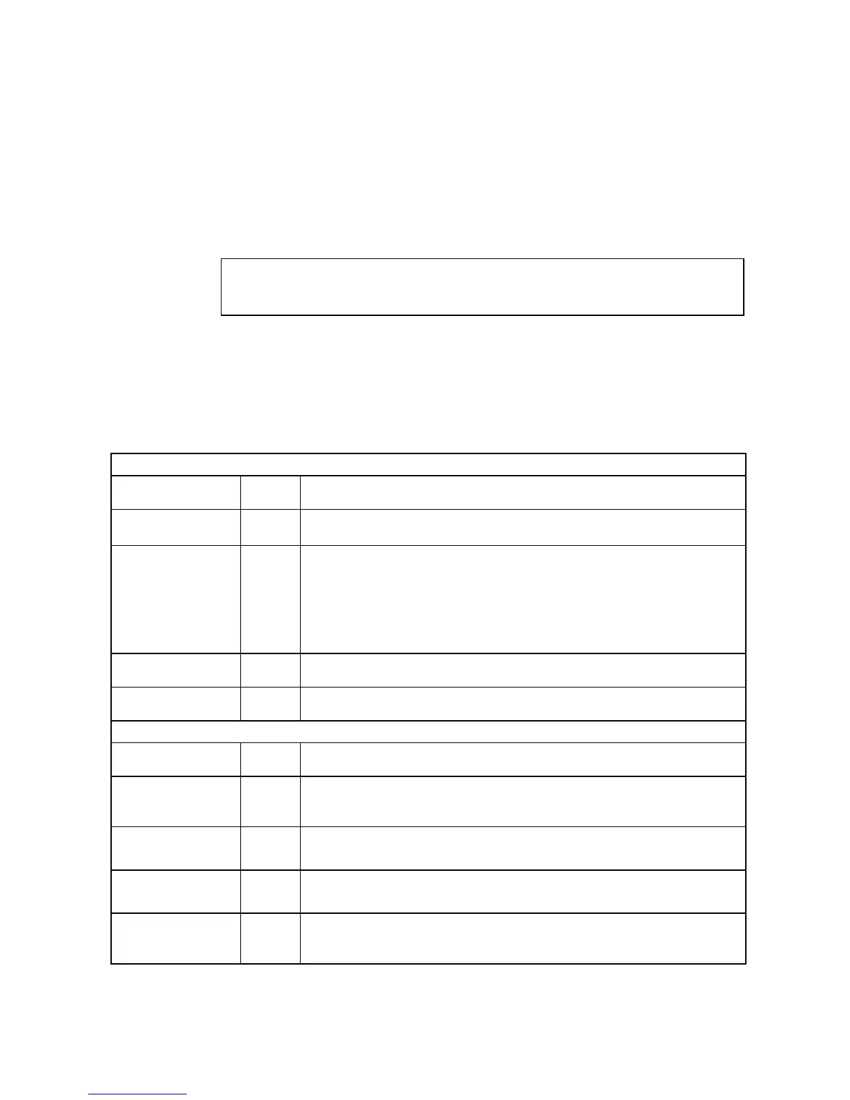
The table below lists the types of system I/O signals.
Types of System I/O Signals (Standard type of controller)
Fixed by system
Type
No. of
points
Function
System input 4
External Emergency Stop 1, External Emergency Stop 2,
Enable Auto, Step Stop (All tasks)
System output
13
(Note)
Auto Mode, Robot Initialized, Robot Running, CPU Normal,
Robot Error, Operation Preparation Completed, Battery Warning,
Emergency Stop 1, Emergency Stop 2,
Deadman SW 1 [Enable SW 1], Deadman SW 2 [Enable SW 2],
Pendant Emergency Stop 1, Pendant Emergency Stop 2,
Continue Start Permission (selectable by I/O hardware setting)
(See Note below.)
Input for command
execution
7 Command (3 bits), data area (3 bits), and Strobe Signal
Output for command
execution
1 Command Processing Completed
Controlled by user program
Type
No. of
points
Function
User input 8
Inputs to read the external I/O status with an IN command or IO [ ] variable.
Used for analysis condition identification, condition satisfaction wait, data
input from the external device, etc.
User output
8
(Note)
Outputs to issue a signal to the external device during program execution
with SET and RESET commands, etc.
HAND input
8
Inputs to read the external I/O status with an IN command or IO [ ] variable.
Used for checking the hand status.
HAND output 8
Outputs to issue signals to the external devices with SET and RESET
commands, etc.
Used for controlling the hand to open or close.
Note: Terminal #53 on CN5 (port 24) is assigned a user output by factory default. It can be assigned the
Continue Start Permission output signal with the I/O hardware setting.