64
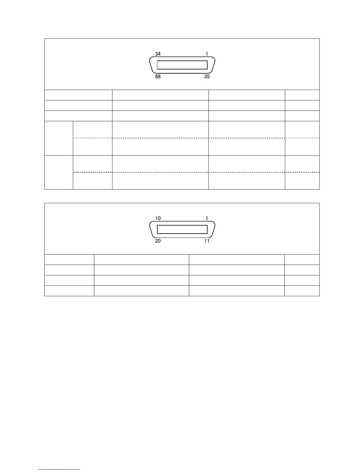
Mini I/O connector (CN5)
View from the cable side
Terminal Number Name Meaning Check point
1 to 3 +24V internal power source terminal +24V internal power output (1)
45 to 60 Signal output terminal 0V (GND) at output (2)
External power
source
+24 VDC power source input 24 VDC power input (1)
32 to 34
Internal power
source
+24 VDC power source output 24 VDC power output (1)
External power
source
0 VDC power source input DC power input (GND) (1)
66 to 68
Internal power
source
0 VDC power source output DC power output (GND) (1)
HAND I/O connector (CN9)
View from the cable side
Terminal Number Name Meaning Check point
1 to 8 Hand output terminal 0V (GND) at output (2)
17 Internal power source output (+24V) 24 VDC power output (1)
18 Internal power source output (0V) DC power output (GND) (1)