Instructions for use Carina SW 3.2n 29
Operating concept
Screen
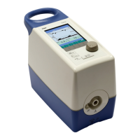
Structure of the screen
A Alarm line with the following information:
– Symbol for suppressed acoustic alarm sig-
nal or symbol for deactivated alarm limit
– Alarm message
B Status line for current device settings.
C Display for real-time waveforms of flow and
pressure or bar graph for pressure and
4 measured values
D Display for 2 measured values (value 1,
value 2), configurable
E Information line, e.g., for information when the
limit of the setting range is reached.
F Display of functions and ventilation parameters.
The display is activated by the associated key.
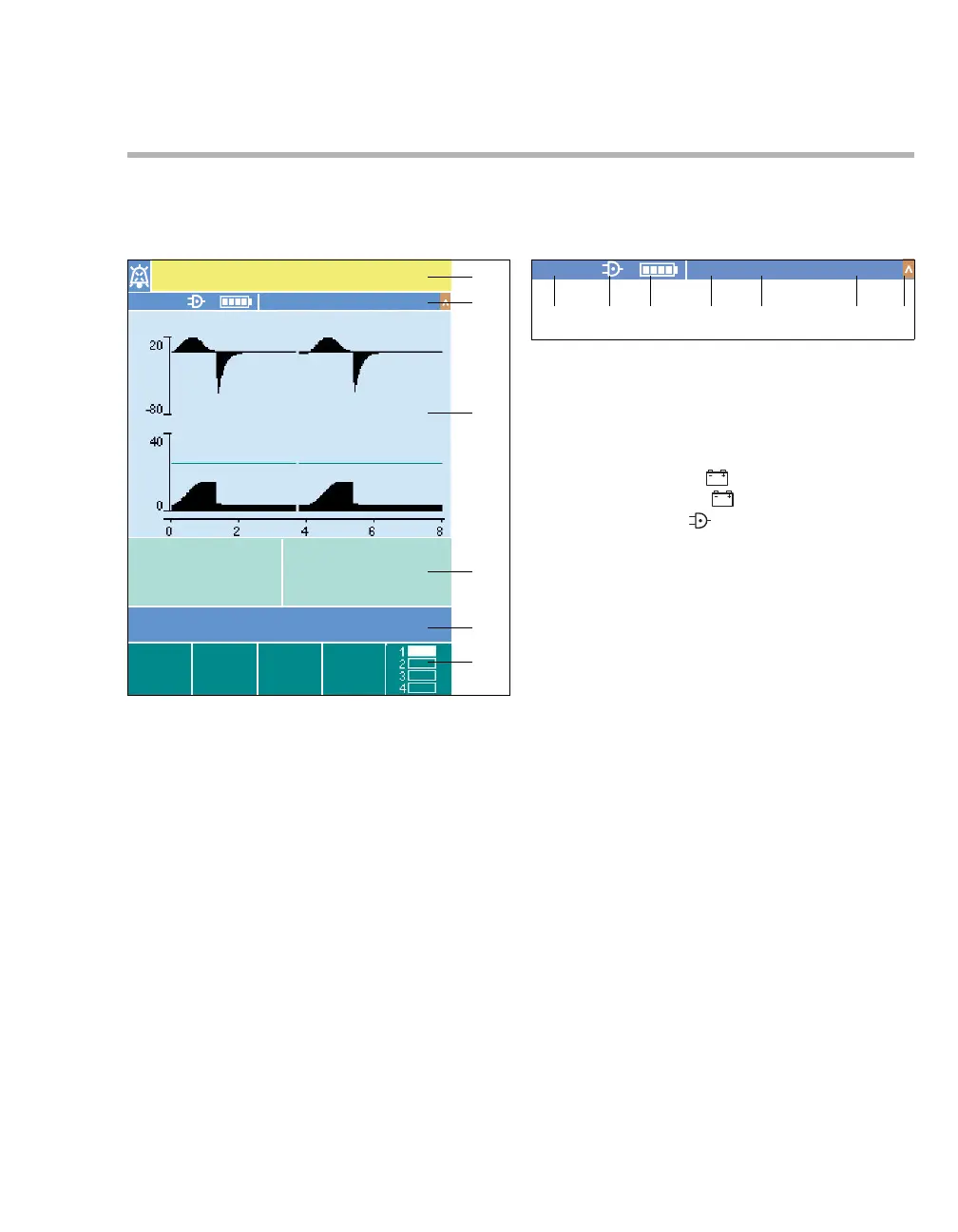
Status line for current device settings
A When configured, display of LPO if the O2 sup-
ply comes from a low-pressure oxygen supply.
If LPO is not displayed, the O2 supply is from a
HPO supply.
B Power supply:
– Internal battery
– External battery
– Mains power
C Charge state of internal battery
D Breathing circuit:
– Expiratory valve ExpV
– Leakage valve LeakV
E Application mode:
– NIV
– Tube
F Set ventilation mode:
–VC-SIMV
–VC-AC
–PC-BIPAP
–PC-AC
– SPN-CPAP/PS
G Display for detection of spontaneous breathing
activity
500
A
B
C
D
E
F
Check settings !!
NIVLeakV
SPN-CPAP/PS
Flow
Pressure
L/min
mbar
211
NIVLeakV
SPN-CPAP/PS
ABC DE FG
int
ext
 Loading...