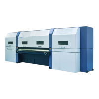
Rho 1012/1030 EOperation
The table of the stacking unit can be moved manually in vertical direction
during manual mode.
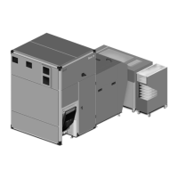
1 Pressure indicator
2 Adjusting screw
3 Control knob
4 UP/DOWN buttons
5Selectorswitch
6 Blow Air Left/Blow Air Right
7 Emergency-Stop switch
1
2
3
6
7
4 5
Fig. 34 Operating elements
The operating elements at the operator panel have the following function:
Position
Operating element
Function
1 Pressure indicator Indicates the a ir pressure at the
compressed-air nozzles
2 Adjusting screw Adjusting the light barrier
3
Control knob
Adjusting the air pressure at the compressed-air nozzles
4
UP/DOWN buttons Moving the table manually up or down (only possible in
manual mode)
5
Selector switch Switching between automatic and manu al mo de
6
Blow Air Left/B
low Air Rig ht
Adjusting the c
ompressed-air distribution to the left- and
right-hand s
ide
7
Emergency-Stop switch
Triggering an emergency stop
2004 – 2013 © Durst Phototechnik AG – www.durst-online.com , Rho 1012/10 30 , Issued 07/2013 67 / 147