SV-EMS-220 Installation and Configuration
SkyView System Installation Guide - Revision K 7-35
FloScan 201B sensor only: make note of the numbers on the tag (pulses / gallon)
attached to the fuel flow sensor.
Dynon Avionics supplies the
Electronics International FT-60
(Dynon P/N 100403-003) fuel flow
transducer. Dynon no longer
supplies the FloScan 201B, but
SkyView is compatible with this
sensor.
The SV-EMS-220 supports
differential fuel flow sensor
installations in Rotax 912 and 914
installations as illustrated in Figure
35.
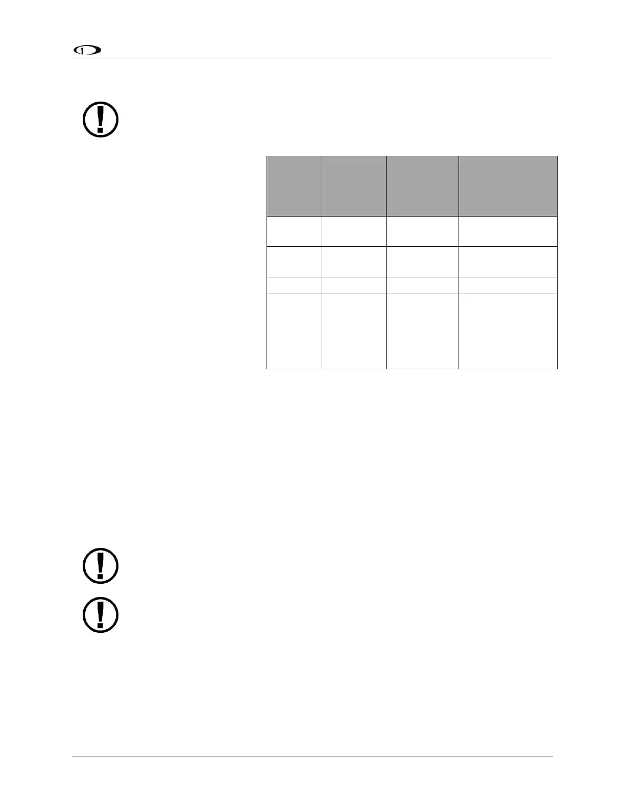
Table 34 revisits which SV-EMS-220
pins are compatible with fuel flow
sources.
General Placement Recommendations
When placing either sensor, ensure that the three wire leads are pointed straight up. A filter
should be placed upstream from the sensor to screen out debris. Placement of the fuel flow
sender relative to other items in the fuel system like fuel pumps is left to the builder. It is not
uncommon, though, to place the sender downstream of any auxiliary electric boost pumps but
upstream of the engine driven fuel pump. The Fuel Flow Transducer, hoses and fittings should
NOT be installed next to the exhaust system or a turbocharger. Excessive heat can damage fuel
system components. For best measuring performance, the fuel should travel uphill by one to
two inches after leaving the fuel flow sender.
Due to vibration issues, never connect the sensor directly to the engine.
Do not use Teflon tape when screwing in any of the fittings.
EI “Red Cube” Installation
The Electronics International “Red Cube” FT-60 flow transducer has ¼” female NPT ports. Do
not exceed a torque of 300 inch-lbs. when installing fittings into the transducer. The Red Cube
FT-60 should NOT be installed with its wires pointing DOWN (the best situation is with the wires
pointing UP). The fuel line on the outlet port should not drop down after exiting the transducer.
Fuel Flow
Sensor
Wire
Color
Fuel Flow Input 1
(From fuel tank)
Fuel Flow Input 2
for optional 2
nd
transducer
(Return to fuel
tank)
Table 34–SV-EMS-220 Fuel Flow Connections