Autopilot Servo Installation, Configuration, and Calibration
SkyView System Installation Guide - Revision K 10-15
Maximum Bank Angle
The maximum bank angle parameter specifies a maximum bank angle which the autopilot will
not exceed during turns. An appropriate maximum bank angle protects against overbank
conditions. If the maximum bank angle is reached during a turn, the autopilot limits the bank to
that value and then reduces it as needed to complete the turn.
If the maximum bank angle is reached, the turn rate target is ignored until the aircraft returns
to within 5° of level in the roll axis.
To derive an appropriate maximum bank angle, calculate the bank angle that results from your
desired turn rate limit and cruising airspeed. Then set the maximum bank angle to at least 5°
above this value. If you are not comfortable with this bank, decrease the turn rate target. The
bank angle minimum is 5° and the maximum is 45°. Its default value is 35° and it is adjustable in
1° increments.
To adjust the maximum bank angle:
1. Go to the Roll Axis Maximum Bank Angle Page (SETUP MENU > AUTOPILOT SETUP >
ROLL AXIS > MAXIMUM BANK ANGLE).
2. Adjust the maximum bank angle.
3. Press ACCEPT to save the value or press CANCEL to return to the Roll Axis Menu.
Turn Rate Target
The turn rate target parameter specifies the desired average turn rate for autopilot-
commanded turns. For example, a setting of 3.0°/SEC will ideally complete a 90° turn in 30
seconds. Due to flight dynamics and the time it takes the autopilot to initiate a turn, there may
be points during a turn where the turn rate target is exceeded. Turn rate target is specified in
degrees per second (°/SEC). The minimum turn rate target value is 0.5°/SEC and the maximum
is 3°/SEC. Its default value is 1.5°/SEC and it is adjustable in 0.1°/SEC increments.
To adjust the turn rate target:
1. Go to the Roll Axis Turn Rate Target Page (SETUP MENU > AUTOPILOT SETUP > ROLL
AXIS > TURN RATE TARGET).
2. Adjust the turn rate target value.
3. Press ACCEPT to save the value or press CANCEL to return to the Roll Axis Menu.
Pitch Axis Configuration
Pitch Axis Torque
The pitch axis torque parameter specifies how much torque the pitch servo will exert before
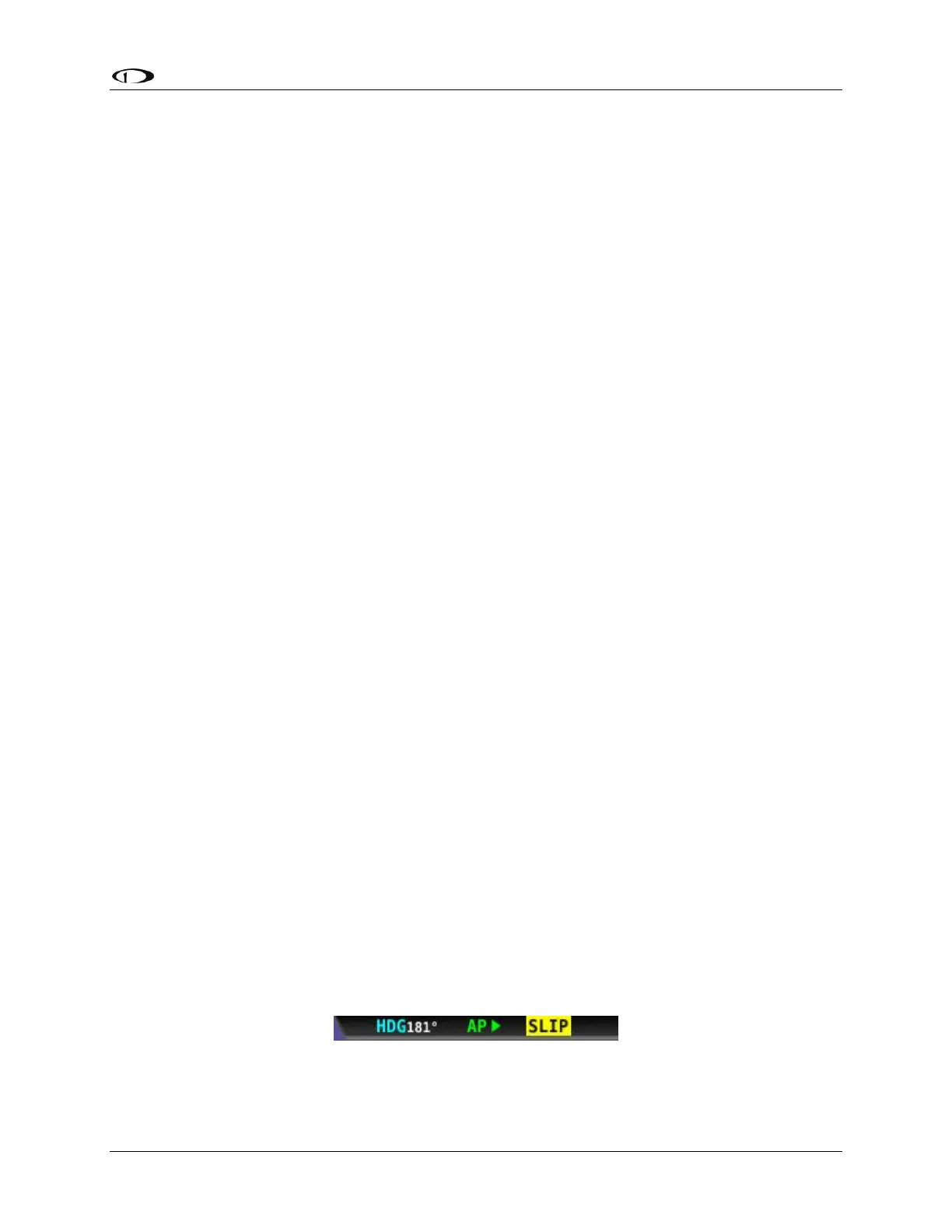
slipping. Servo slip is indicated by the word SLIP in black letters in a yellow box on the Top Bar
for the pitch axis as shown in Figure 58.
Figure 58–Example Pitch Axis Servo Slip Warning