SV-D700 / SV-D1000 Installation and Configuration
4-12 SkyView System Installation Guide - Revision K
information to your transponder for this functionality to work correctly.
It is the installer’s responsibility to determine how to connect external serial devices to the
display using the included wire harness. Installers should reference serial device documentation
for serial port specifications. The basic order for installing an external serial device is as follows.
1. Specify a serial port for the device.
2. Make the serial port electrical connection. If you have multiple SkyView displays, each
serial port transmit and/or receive wire to or from a serial device should be connected
to each display in parallel.
3. Configure the serial port on each D700 or D1000 (under SETUP MENU > LOCAL DISPLAY
SETUP > SERIAL PORT SETUP) according to the device’s documentation. Note that each
SkyView display’s serial ports need to be configured individually.
4. When serial port configuration is complete for all serial devices and displays, perform a
final check by doing the following:
a. Power down all displays except #1. Verify all serial port devices are working -
transponder, GPS, radios, etc.
b. Power down all display except #2. Verify all serial port devices are working -
transponder, GPS, radios, etc.
c. Continue for additional displays if installed.
A SkyView Display serial port can be configured to communicate with one device
on its TX and a different device on its RX, but when doing so, the TX and RX speeds
must be the same.
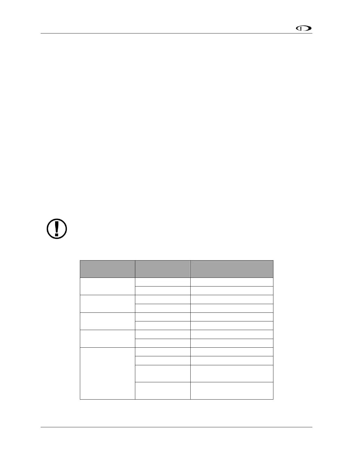
Table 10 contains serial port wire functions and wire harness colors.
SkyView Display Harness
Wire Colors
Yellow with Orange stripe
Yellow with Violet stripe
Table 10 - SkyView Serial Port Connections