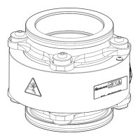
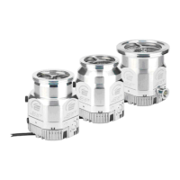
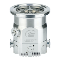
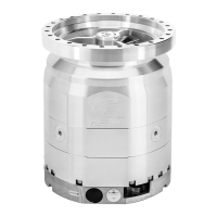
Earth (ground) connecons
Edwards recommend ng a separate earth (ground) conductor to earth the nEXT85 pump.
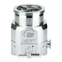
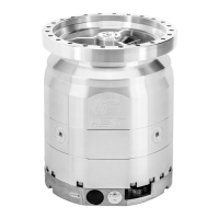
Earth the pump using the connecon provided. Refer to Figure 11 on page 84, Figure 12 on
page 85, Figure 13 on page 85 and Figure 14 on page 85.
Use an uninsulated braid or a separate insulated green/yellow connector and use an M5 x 10
screw and shake-proof washer supplied (ed to the earth hole on the pump) to secure the
earth connector to the pump. The size/rang of this grounding conductor should be large
enough to protect against other equipment within the customer system. The impedance
between the pump body and the earth connecon point must be < 0.1Ω.
TIC or TAG logic interface connecons
If an Edwards TIC Turbo Instrument Controller, TIC Turbo Controller or TAG Controller are used
to power and control the pump, the nEXT85 pump logic interface cable connects directly into
the back of the TIC or TAG. Refer to the TIC or TAG
Instrucon Manuals for further informaon.
The RS485/RS232 slide switch must be in the RS232 posion if either the TIC or TAG is to be
used to control the nEXT85 pump. Refer to Connect the serial interface to the customer control
equipment on page 29. If the switch is in the RS485 posion, the TIC will connect to the pump
in parallel mode, indicang the pump type as nEXTp; the serial connecon will be disabled, but
start and stop will be possible. If the switch is in the RS485 posion, the TAG will not connect to
or control the pump at all.
Connect the logic interface to control equipment
To operate the nEXT85 pump using the customer's own control system, use a suitable
connector mang half (not supplied) to connect the control equipment to the connector on the
logic interface cable.
Refer to Table 43 on page 91. When making the electrical connecons to the nEXT85 pump,
refer to Table 44 on page 93 for full details of the logic interface connector pins.
Connect the electrical supply
WARNING:
This product requires a separate power supply (not included). The power supply should be
adequately protected against a hazardous live condion (for example, in case of a short
circuit).
WARNING:
Incorporate a suitable Emergency Stop Switch in the electrical supply. Locate the switch in
an easily accessible posion and mark it as the emergency disconnecng device for the
pump. Failure to do so will result in not being able to switch o the pump in an
emergency.
WARNING:
Incorporate a suitable fuse or current liming device in the 24 - 48 V d.c. supply line to the
pump. If this is not done and a fault develops, the pump may develop a hazardous surface
temperature or present a re hazard.
B8G0-00-880A - Install the nEXT85
Page 26
 Loading...
