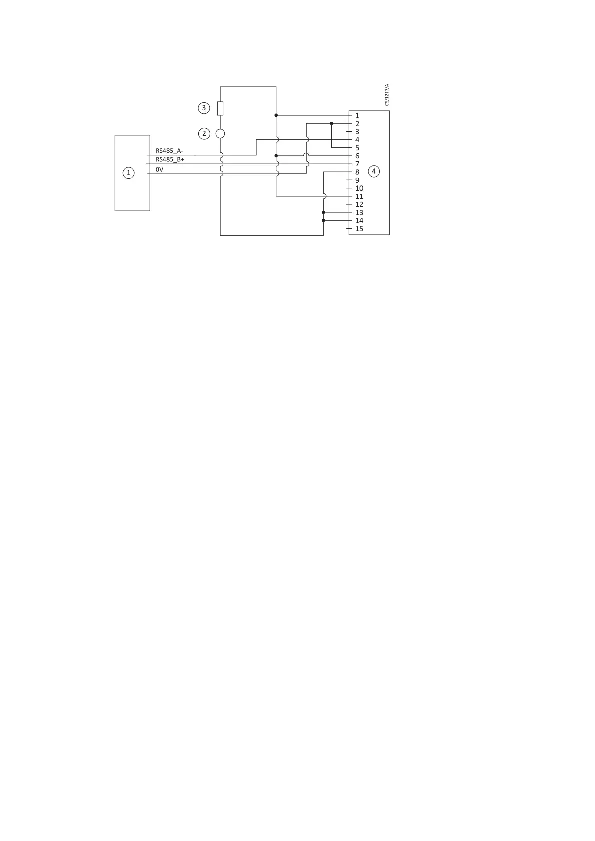
Figure 6
Logic interface connecons - RS485 serial control
1. RS485 interface on control equipment
2. 24-48 V d.c. electrical supply
3. Fuse
4. nEXT pump logic interface
Serial enable
To send a serial message over the serial link, serial enable must rst be acvated.
Link the serial enable input signal (pin 5) to pin 2 of the customer logic interface mang half.
Edwards recommends incorporang this link into the serial communicaons cable so that the
serial enable is only acvated when the serial cable is connected. When the cable is removed,
serial enable will become inacve.
Serial enable acts as an interlock for start commands sent over the serial interface. If the pump
is running in serial control mode (having been sent a serial start command) and the serial
enable subsequently becomes inacve, the pump will trigger a fail condion and will
decelerate to rest. To clear this fail condion, re-acvate the serial enable and send a serial
stop command.
Connecon for mixed parallel and serial operaon
The pump can be controlled using parallel interface control inputs and at the same me
monitor various pump parameters using the serial interface or the USB service port using the
Edwards nST PC soware. Alternavely, the pump can be controlled using commands sent over
the serial interface while at the same me monitor the normal signal and analogue output over
the parallel interface.
Figure 7 on page 32 shows a schemac diagram of a system that demonstrates how to do
this. This connecon is a hybrid of the parallel and serial connecon which are described in
detail in Connect the parallel control and monitoring on page 27 and Connecon for serial
control and monitoring on page 28 respecvely. Many of the opons described in those
secons are available in mixed parallel and serial operaon but note that whilst serial enable is
acve to enable the serial link, the parallel standby and fail signals are not available. The mul-
drop connecon shown in Figure 7 on page 32 can also be used with mixed parallel and serial
operaon.
The pump cannot be controlled using both the parallel and serial interfaces simultaneously. For
example, if the pump is started by sending a start command over the serial interface, the pump
cannot then be stopped by using the start /stop switch on the parallel interface. The pump will
ignore the state of the start / stop switch on the parallel interface. To stop the pump, send a
serial stop command. Only when the serial stop command has been received by the pump can
any commands sent via the parallel interface be acted on.
B8G0-00-880A - Install the nEXT85
Page 31