Logic interface items
OK
On (< 0.1 V d.c. sinking 1.7 mA,
< 0.8 V d.c. sinking 20 mA)
Current rang 20 mA to 0 V
Voltage rang 28.8 V d.c. maximum external pull up voltage
*
Mang half of connector not supplied.
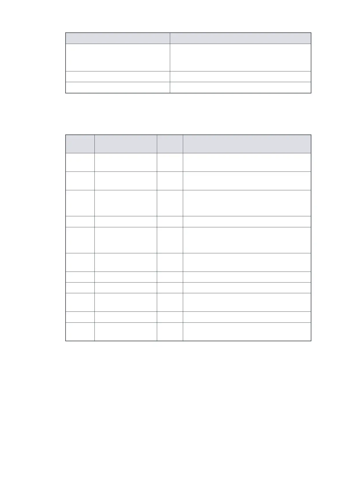
Refer to the following table for Logic Interface connector pins for the electrical connecons.
Table 44
Logic interface connector pins
Pin
number
Signal Polarity Use
2 0 V Control reference - 0 V reference for all control and status signals
below.
3 START/STOP control
input
- Connect to Pin 2 to start pump.
4 STANDBY control
input / Serial RX/
RS485 A-
- Connect to Pin 2 to enable standby speed when
serial enable is inacve and RS485/RS232 switch
is in the RS232 posion.
5 Serial enable - Connect to Pin 2 to enable the serial link.
7 FAIL / Serial TX/RS485
B+
- Logic high when fail condion exists and serial
enable is inacve and RS485/RS232 switch is in
the RS232 posion.
9 Analogue output Posive 0 - 10 V output proporonal to measured
output.
10 Chassis / Screen - Screen
12 Chassis / Screen - -
15 NORMAL status output - Logic low when pump rotaonal speed is at
normal speed or above
8, 13, 14 Electrical supply: 0 V - -
1, 6, 11 Electrical supply: 24 -
48 V d.c.
Posive -
B8G0-00-880A - Technical Reference
Page 93