Note:
The RS485/RS232 slide switch must be in the (default) RS232 posion to use the standby or
fail parallel interface signals, refer to Connect the serial interface to the customer control
equipment on page 29.
2. To monitor analogue output, connect the customer control equipment to the pump
analogue output (pin 9) and to pin 2 of the customer logic interface mang half.
When the pump is shipped, the analogue output is congured to monitor pump
rotaonal speed. To monitor other parameters, re-congure the nEXT85 pump using
commands over the Serial Interface. Refer to Connecon for serial control and
monitoring on page 28 for further details.
3. To monitor the normal status output, connect the customer control equipment to the
normal status output (pin 15) and to pin 2 of the customer logic interface mang half.
The output can be used to control other devices in the pumping system. The output
can drive a low power relay of up to 24 V d.c. coil rang (up to 20 mA).
4. To monitor the fail status output, connect the customer control equipment to the fail
output (pin 7) and to pin 2 of the customer logic interface mang half.
The output can be used to control other devices in the pumping system. The output
can drive a low power relay of up to 24 V d.c. coil rang (up to 20 mA).
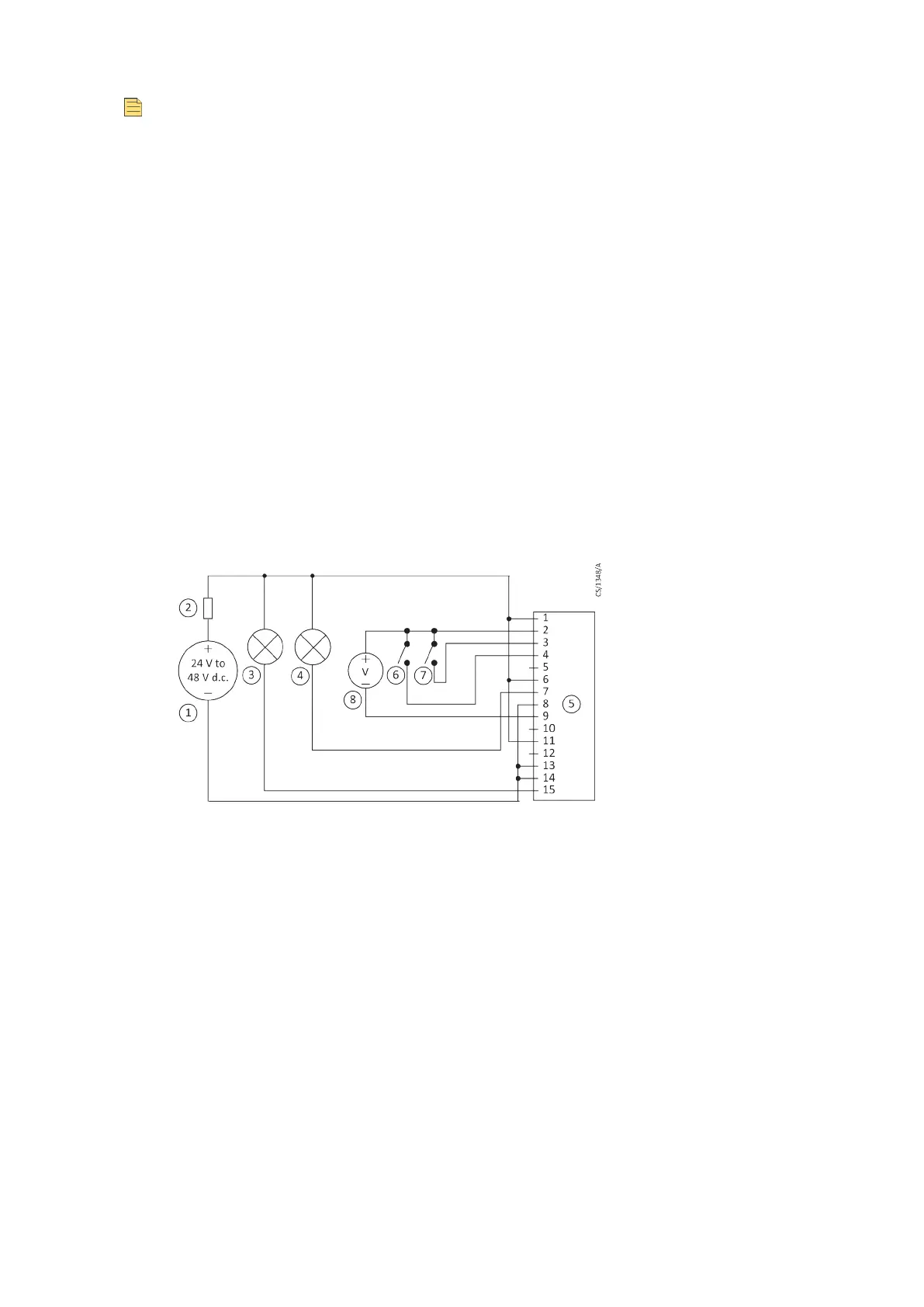
Figure 3
Logic interface connecons - parallel control
1. 24 - 48 V d.c. electrical supply
2. Fuse
3. Oponal indicator - system OK
4. Oponal indicator - normal speed
5. nEXT pump logic interface
6. Start switch
7. Oponal standby switch
8. Oponal voltmeter to monitor analogue
output
Connecon for serial control and monitoring
The serial interface allows the nEXT85 pump to be controlled and to be interrogated as to its
operaonal status using a number of serial commands or the nST PC soware. There is also a
mul-drop mode that allows for the connecon of more than one nEXT85 pump to a single
serial port on the control system.
B8G0-00-880A - Install the nEXT85
Page 28