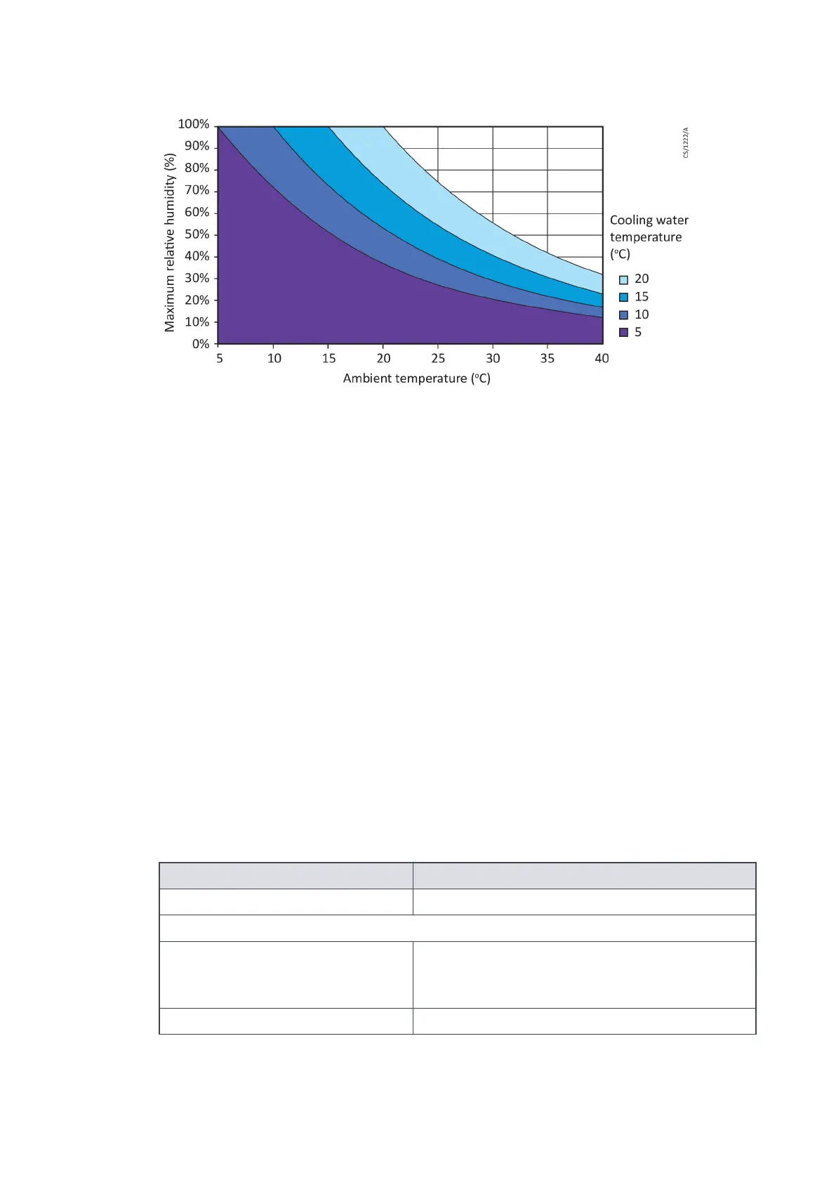
Figure 16
Maximum relave humidity to avoid condensaon with water cooling
Electrical data
The nEXT85 pumps can be driven by either the customers system or by the Edwards TIC Turbo
Instrument Controller, TIC Turbo Controller or TAG Controller.
If using the customer system, an appropriate, pre-approved, UL/CSA rated 24 - 48 V d.c. power
supply should be used. The size of the power supply required depends on the applicaon and
the power limit congured in the nEXT85 pump. The power limit seng determines how
quickly the pump ramps up and dictates the size of the power supply required. If serial
communicaons is available, the power limit seng of the nEXT85 pump can be selected.
Refer to Table 43 on page 91 for the maximum power limit sengs for nEXT85 pumps. If the
applicaon requires rapid cycling of the pump, faster ramp mes can be achieved if the power
supply delivers higher current, up to a maximum in accordance with Table 43 on page 91.
If the facility to adjust the power limit seng is not available, use a power supply capable of
delivering enough current to meet the Edwards factory default power limit seng, shown in
Table 43 on page 91.
Logic interface connector
nEXT85 pumps have a 15-way logic interface connector on the end of the logic interface cable.
Use a suitable connector mang half (not supplied) to connect the nEXT85 pump to the
customer equipment. Refer to the following table for the connector mang half type.
Table 43
Logic interface technical data
Logic interface items
Connector
*
15-way D-type male
nEXT85 pumps electrical supply:
Allowable voltage range
(including any ripple)
24 V d.c. to 48 V d.c. +5%, -10%
(21.6 V d.c. to 50.4 V d.c.)
Maximum voltage ripple 0.5 V rms
B8G0-00-880A - Technical Reference
Page 91