Similarly, if the pump is started by using the start switch on the parallel interface, the pump
cannot then be stopped by sending a stop command over the serial interface. The pump will
ignore any start or stop commands received over the serial interface. To stop the pump, use
the parallel stop switch. Only when the pump has been stopped using the parallel interface
switch will any start or stop commands be accepted via the serial interface.
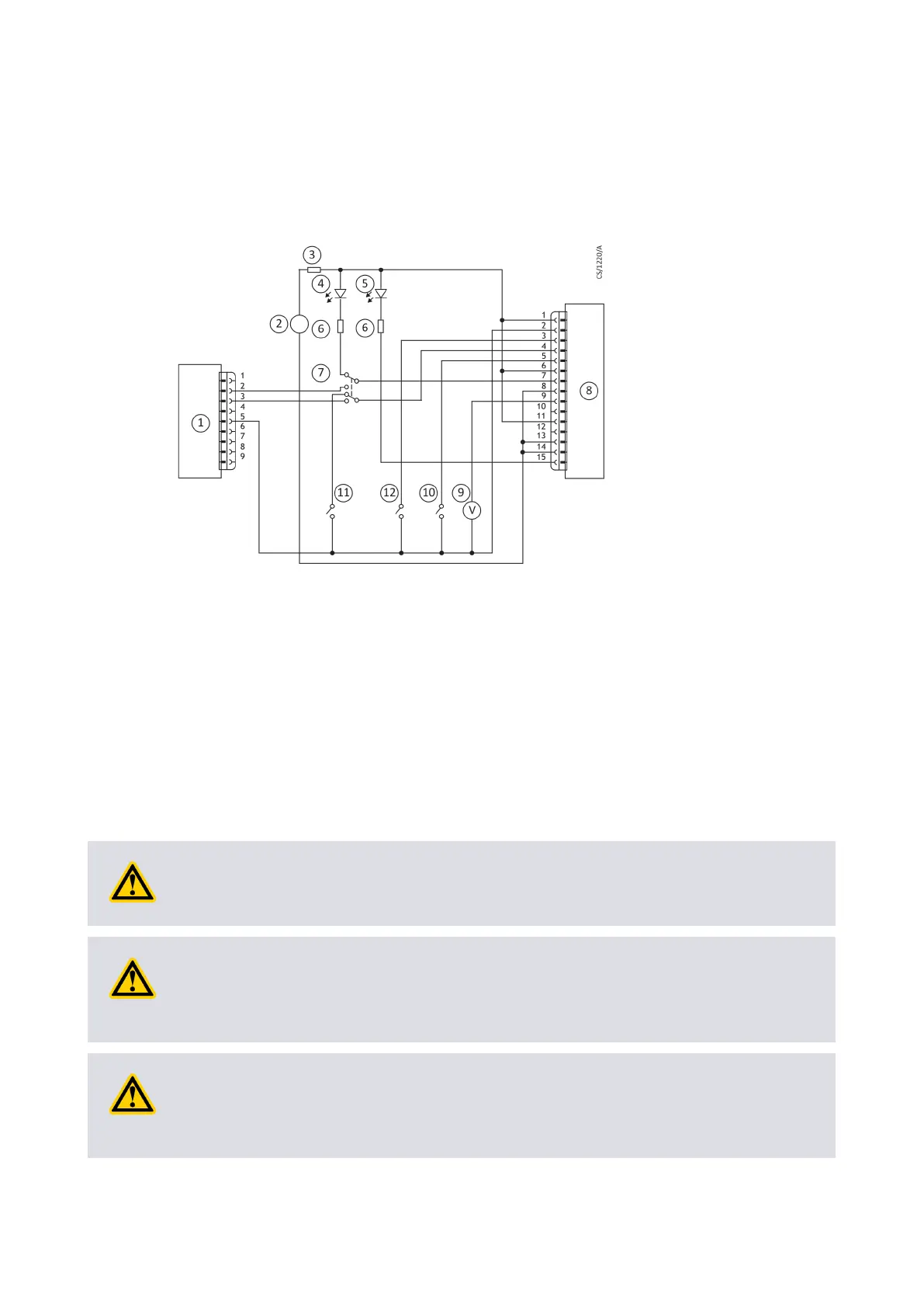
Figure 7
Logic interface connecon - mixed parallel and serial operaon
1. RS232 interface on control equipment
2. 24 V d.c. electrical supply
3. Fuse
4. Oponal LED indicator - system OK
5.
Oponal LED indicator - normal speed
6. Current limit resistor for LED
7. Oponal serial link selector
8. nEXT pump
9. Oponal voltmeter
10. Oponal serial enable switch
11.
Oponal standby switch
12. Start switch
Cooling
Cooling requirements
CAUTION:
Ensure that the pump is adequately cooled to prevent damage to the rotor and bearing.
CAUTION:
When using alternave cooling arrangements other than the standard Edwards cooling
accessories, ensure cooling is not solely directed or ducted onto the pump controller.
CAUTION:
If the pump will be located inside an enclosure, ensure that there is adequate venlaon
so that the ambient temperature around the pump does not exceed 40 °C.
B8G0-00-880A - Install the nEXT85
Page 32