Figure 4
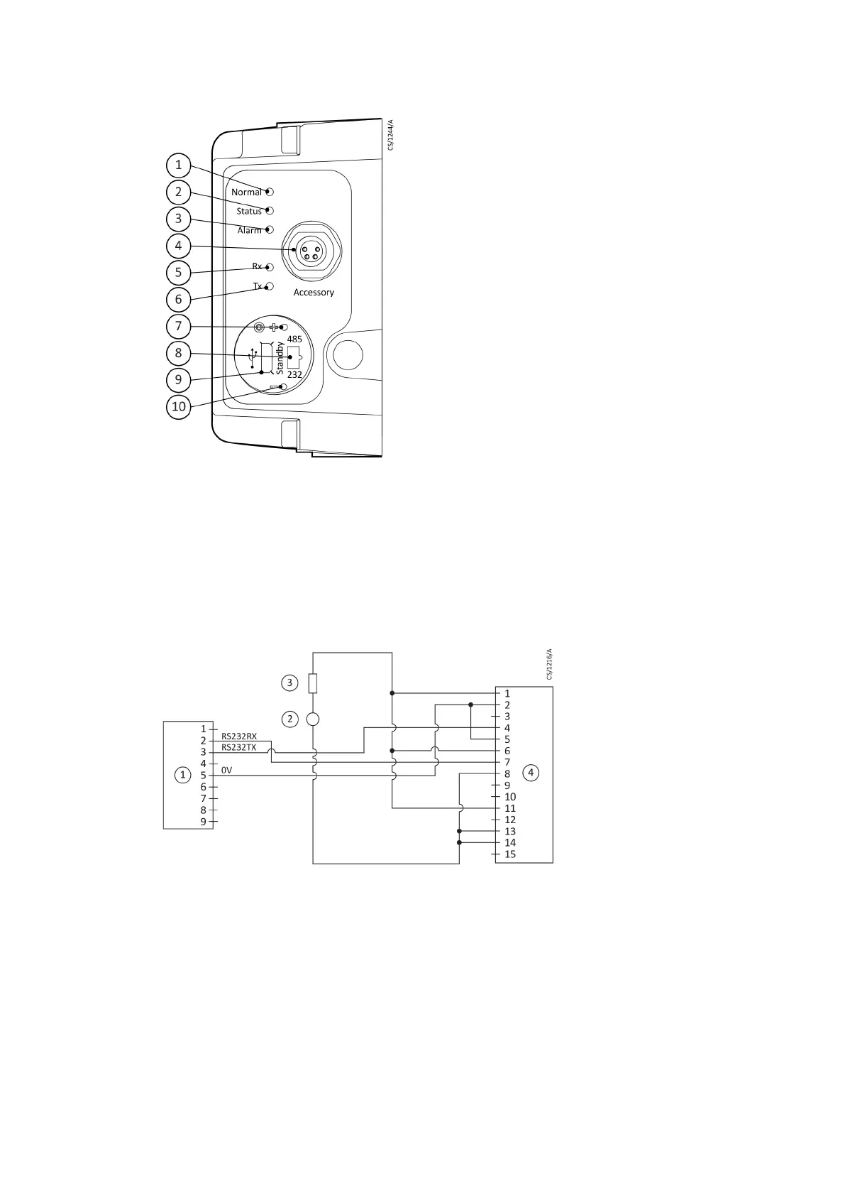
Motor controller status informaon
1. Normal LED
2. Status LED
3. Alarm LED
4. Accessory connector
5. Serial receive LED
6. Serial transmit LED
7. Standby speed increase buon
8. RS232/RS485 slide switch
9. USB connector
10. Standby speed decrease
buon
Figure 5
Logic interface connecons - RS232 serial control
1. RS232 interface on control equipment
2. 24-48 V d.c. electrical supply
3. Fuse
4. nEXT pump logic interface
B8G0-00-880A - Install the nEXT85
Page 30