List of Figures
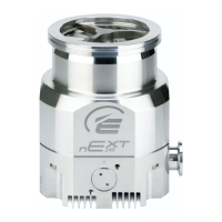
Figure 1: Typical pumping system with a nEXT pump..................................................................20
Figure 2: Allowable pump
orientaon.........................................................................................24
Figure 3: Logic interface connecons - parallel control...............................................................28
Figure 4: Motor controller status informaon............................................................................ 30
Figure 5: Logic interface
connecons - RS232 serial control....................................................... 30
Figure 6: Logic interface connecons - RS485 serial control....................................................... 31
Figure 7: Logic interface connecon - mixed parallel and serial operaon ................................. 32
Figure 8: Auxiliary interface
connecon...................................................................................... 47
Figure 9: Serial and parallel control owchart.............................................................................53
Figure 10: Accessories................................................................................................................. 79
Figure 11: Dimensions - nEXT85 ISO63........................................................................................84
Figure 12: Dimensions - nEXT85 CF63......................................................................................... 85
Figure 13: Dimensions - nEXT85 ISO100......................................................................................85
Figure 14: Dimensions - nEXT85 DN40........................................................................................ 85
Figure 15: Max allowed rate of pressure rise during
venng: pressure against me (pump
inially at full speed).............................................................................................................. 89
Figure 16: Maximum
relave humidity to avoid condensaon with water cooling.................... 91
Figure 17: Interface circuits for nEXT turbo pump controllers.................................................... 94
Figure 18: Conceptual diagram for mul-drop connecon using RS232 interface....................100
Figure 19: RS485 mul-drop connecon................................................................................... 101
Figure 20: Motor controller connector showing pin numbers.................................................. 102
Figure 21: HS1 Form.................................................................................................................. 104
Figure 22: HS2 Form.................................................................................................................. 105
B8G0-00-880A - List of Figures
Page 9
 Loading...
