FloBoss 407 Instruction Manual
Rev 5/00 2-15
DOC0250A
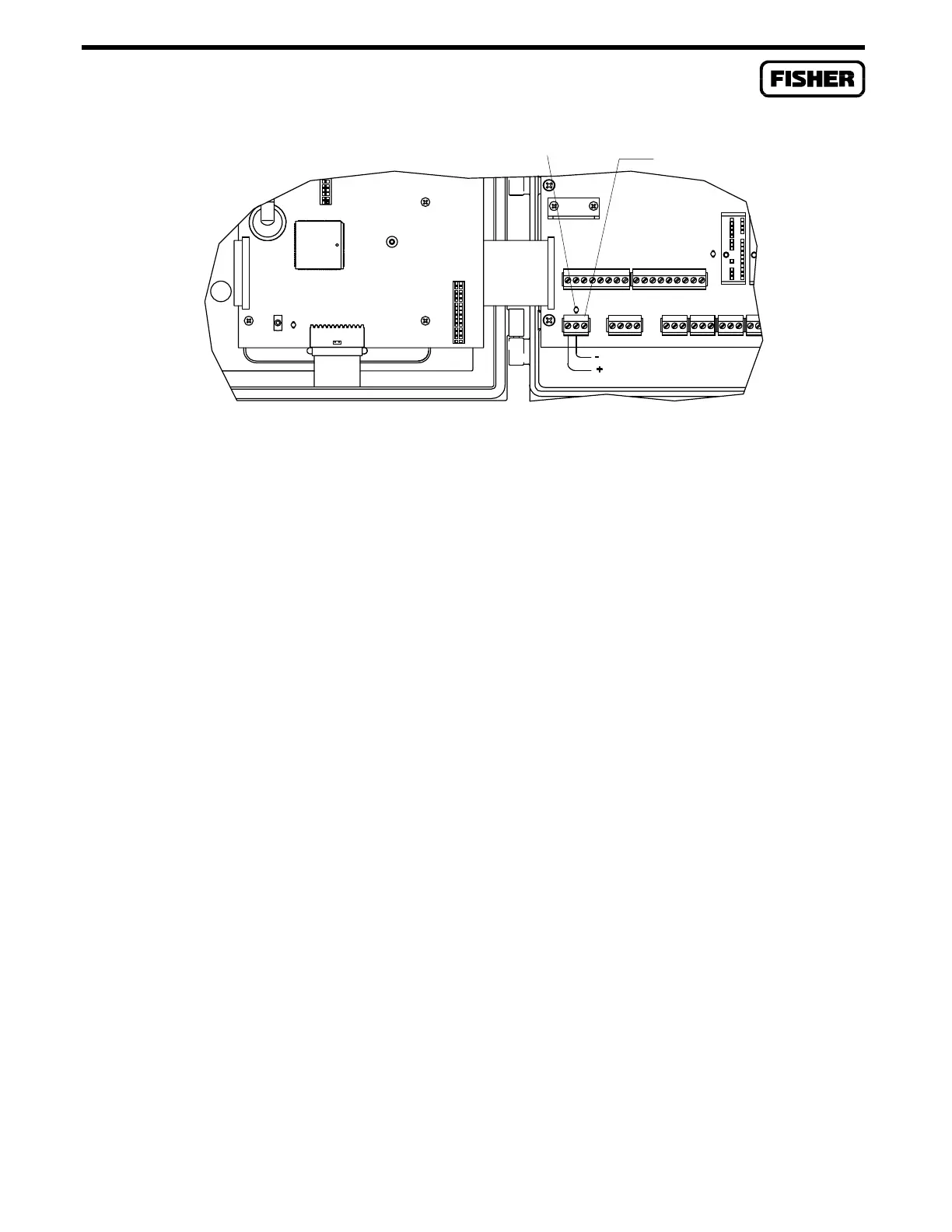
Figure 2-4. Power Wiring Connections
2.4.3 Built-in Analog Input Wiring
Equipment Required: Flat-blade (1/8-inch width) screwdriver
The analog input channels have three field terminals per channel. The “+T” terminal provides +24
volts dc for loop-powered devices. Each channel has a current regulator in series with the “+T”
terminal to provide short-circuit protection. The maximum output of each terminal is 25 milliamps.
The FloBoss 407 is shipped with a 250-ohm scaling resistor between the “+” and “-” analog input
terminals.
The “+” terminal is the positive signal input and the “-” terminal is the negative signal input. These
terminals accept a voltage signal in the 1 to 5 volt range. Since the “-” terminal is internally connected
to common, the analog input channels function as a single-ended input only.
For use with a 4 to 20 milliamp current signal, leave the 250-ohm resistor installed between the “+” and
“-” terminals. Wire the device “+” lead to the FloBoss 407 “+T” terminal and the device “-” lead to the
FloBoss 407 “+” terminal. Figure 2-5 shows the wiring for a typical current signal.
For use as a voltage input, remove the 250-ohm resistor from the analog input terminal block.
Figure 2-6 shows a typical voltage signal analog input.
POWER INDICATOR
POWER TERMINAL BLOCK

 Loading...


