FloBoss 407 Instruction Manual
Rev 5/00 4-11
4.4 CONNECTING COMMUNICATION CARDS TO WIRING
Signal wiring connections to the communications cards are made through the COM2 terminal block
located on the termination card and through TELCO connectors supplied with certain modem cards.
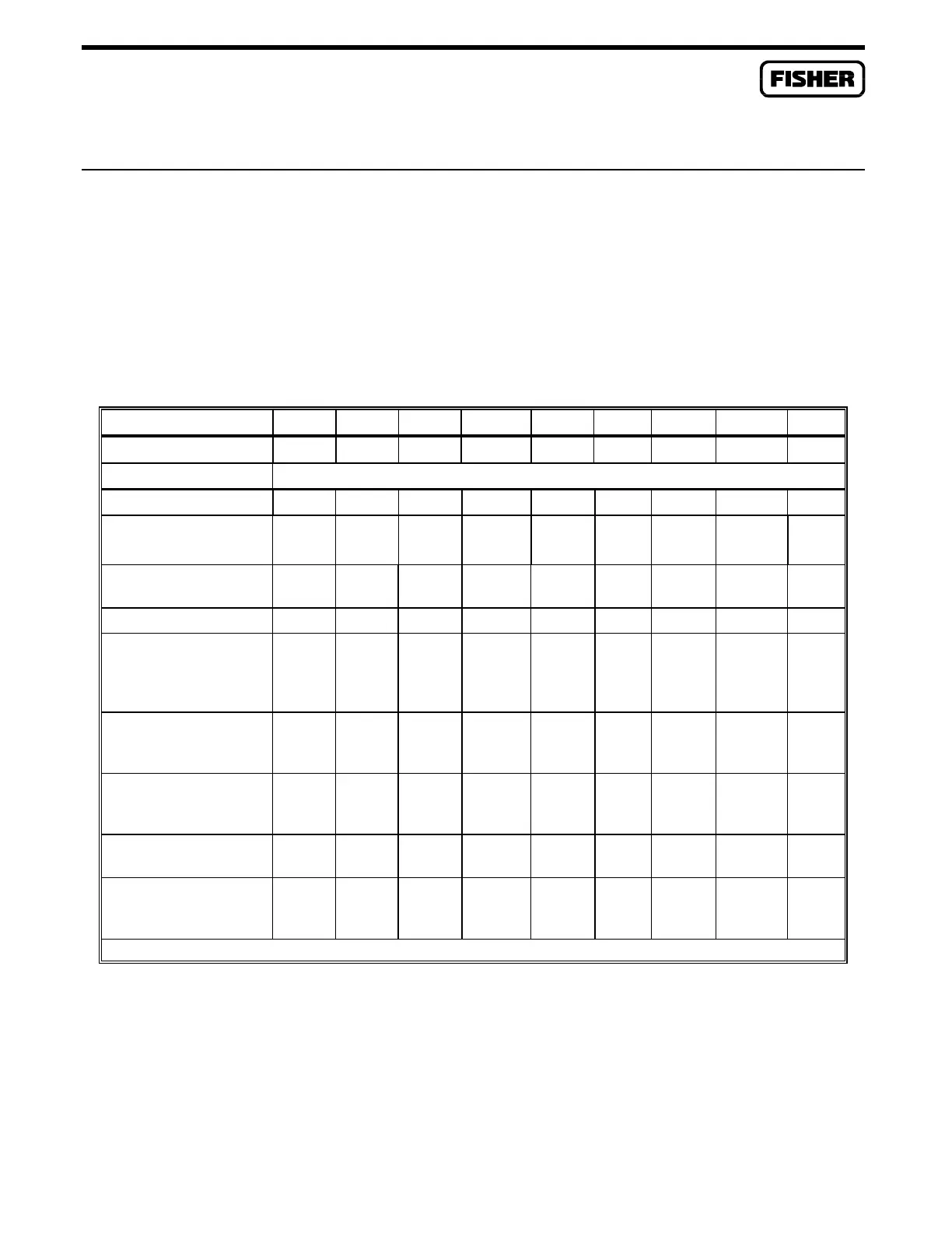
Table 4-4 shows the communications signal connection pin-outs for the COM1 port and the various
communications cards available for the COM2 port on a FloBoss 407.
Table 4-4. FloBoss 407 Communications Signals
Comm Card | Port Pin 1 2 3 4 5 6 7 8 9
COM1 (Built-in RS232) RXD TX RTS CTS DCD DTR
1
DSR COM
COMMUNICATIONS CARDS (For COM2 Only)
EIA-232 Card DCD DSR RX RTS TX CTS DTR RI COM
EIA-422/485 Card –
422 Usage
TX- RX- RX+ TX+
EIA-422/485 Card –
485 Usage
OUT- OUT+
Radio Modem PTT+ RXA PTT- TXA COM
Leased-line Modem –
COM Port,
Private Line Usage
4-Wire or 2-Wire
RXA
or
TIP2
TXTB
or
RING
(1)
RXB
or
RING2
TXTB
or
TIP(1)
Leased-line Modem –
RJ-11 Port,
2-Wire Operation
TIP
(RED)
RING
(GRN)
Leased-line Modem –
RJ-11 Port,
4-Wire Operation
TIP2
(BLK)
TIP1
(RED)
RING1
(GRN)
RING2
(YEL)
Dial-up Modem –
RJ-11 Port
TIP
(RED)
RING
(GRN)
Dial-up Modem –
COM2 Port (output only
for analyzer)
SPK RI RXD SHUT
DOWN
TXD +5V DTR DSR COM
1
Signal is permanently enabled/true.

 Loading...


