FloBoss 407 Instruction Manual
Rev 5/00 3-9
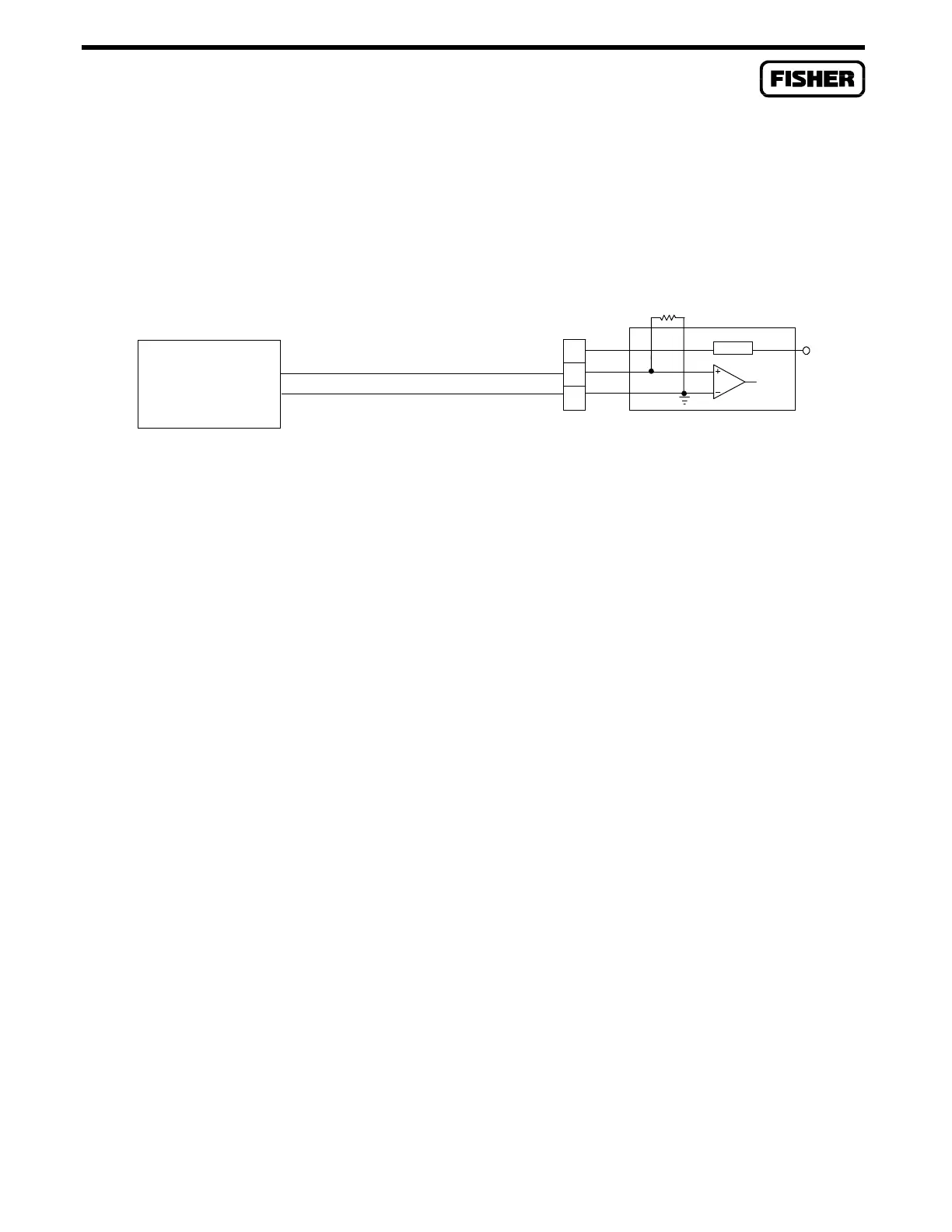
Figure 3-3 shows a typical voltage signal input. Terminal B is the “+” signal input and terminal C is the
“-” signal input. These terminals accept a voltage signal in the 0 to 5 volt range. Since terminal C
connects to a signal ground (non-isolated), the analog input must be a single-ended. Ensure that no
scaling resistor (R1) is installed when the module is used to sense a voltage signal.
+T
B
C
+
R1=OPEN
I LIMIT
AI LOOP
V
S
SIGNAL = 1 TO 5 VDC
SELF-POWERED
VOLTAGE DEVICE
DOC0153A
(modified)
+
-
Figure 3-3. AI Loop Module Field Wiring for Voltage Devices

 Loading...


