FloBoss 407 Instruction Manual
Rev 5/00 4-13
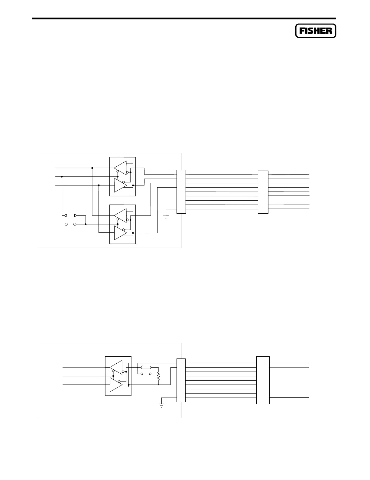
4.4.2 EIA-422/485 Communications Card Wiring
Figure 4-8 shows the relationship between the EIA-422 signals and terminal numbers for the COM2
terminal block. EIA-422 wiring should be twisted pair cable, one pair for transmitting and one pair for
receiving. Jumper P4 in the newer card (Jumper P3 in the older card) is used to control the RTS
transmit function in the EIA-422 mode. This jumper has a default setting of RTS for multi-drop
communications. Placing this jumper in the ON position enables the card to continuously transmit
(such as for point-to-point). This jumper has no effect when the card is wired for EIA-485 operation.
COM2
TERMINAL
BLOCK
EIA-422
-RXD
+RXD
-TXD
+TXD
COM
D
DIR
R
DOC0212T
Mod051000
EIA-422/485 CARD
D
TXD
RTS
RXD
DIR
R
15
22
20
18
23
17
19
24
21
+TRANSMIT
-TRANSMIT
+RECEIVE
-RECEIVE
P2
+5V
P4/P3
RTS
ON
9
4
3
6
8
1
7
2
5
Figure 4-8. EIA-422 Wiring Schematic
Figure 4-9 shows the relationship between the EIA-485 signals and terminal numbers for the COM2
terminal block. Wiring should be twisted-pair cable. On newer design cards, Jumper P3 can be set to
apply (LD) or remove (N/L) a 140-ohm load. Typically, the load would be used in a point-to-point
application, and removed in multi-drop applications, except for one device on each end of the bus.
EIA-422/485 CARD
RTS
TXD
RXD
DIR
D
21
R
COM
20
22
17
23
18
24
19
-OUT
DOC0213A
Mod051000
+OUT
EIA-485
9
5
3
COM2
TERMINAL
BLOCK
TXD
RXD
140
N/L
LD
Note: Jum
er P3 is used for loadin
onl
on newer card.
15
Figure 4-9. EIA-485 Wiring Schematic

 Loading...


