FloBoss 407 Instruction Manual
Rev 5/00 B-3
B.3 MVS MOUNTING
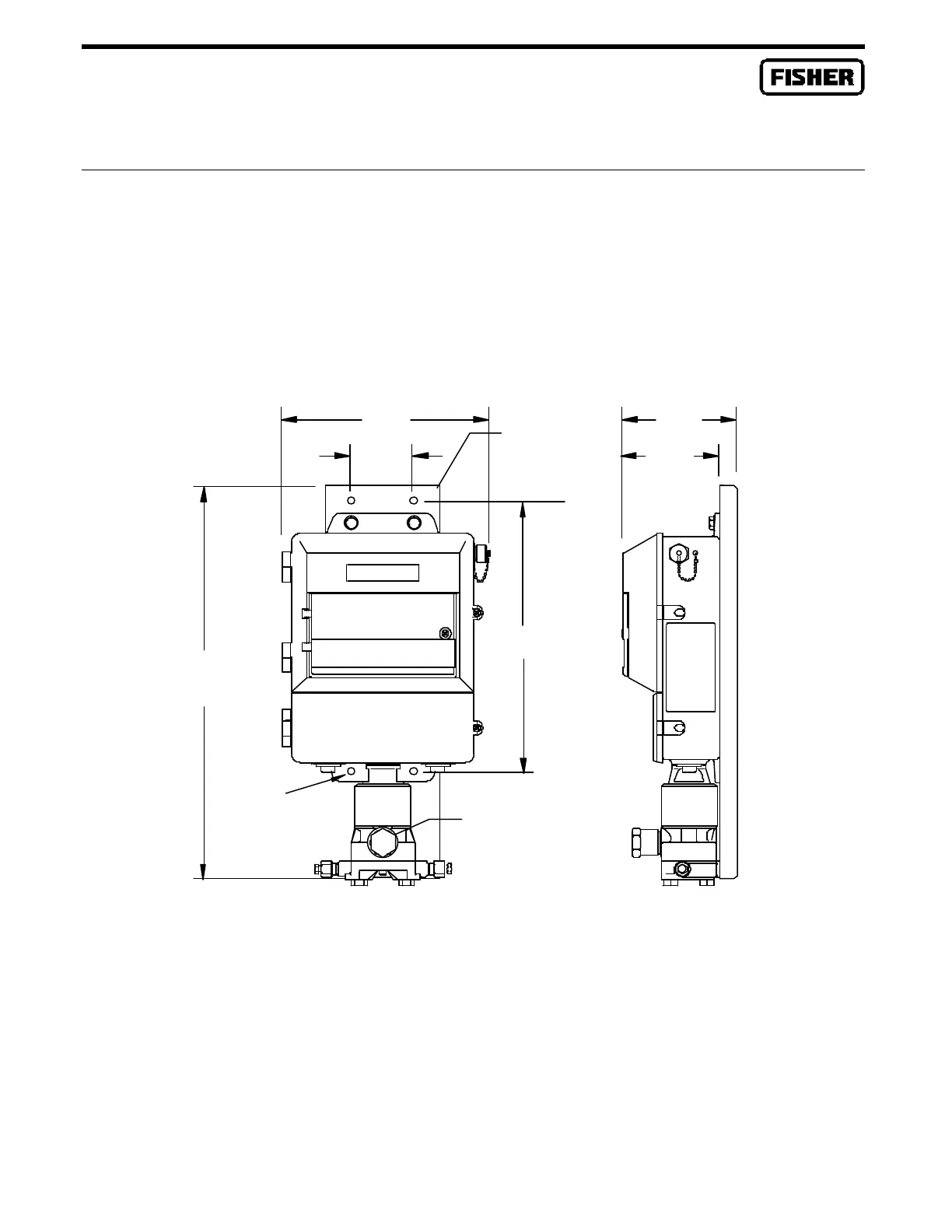
MVS mounting depends on whether it is an Integral or Remote MVS. The Integral MVS205 is factory-
mounted directly to the FloBoss 407 enclosure. This mounting uses a special coupler to join the threads
on the MVS to the center wiring hole in the bottom of the FloBoss 407 enclosure. Refer to Figure B-3,
which shows outline and mounting dimensions. A mounting (stiffening) plate fastened to the MVS and
the FloBoss 407 enclosure provides rigidity to the assembly. In this type of mounting, the MVS
interface circuit is factory-installed inside the lower compartment of the FloBoss 407 enclosure.
.38 DIA MTG
HOLES
DOC0205A
17.95
12.15
9.32
2.81
5.12
4.36
Figure B-3. FloBoss 407 and Integral MVS Outline and Mounting Dimensions
The FloBoss 407 with an integral MVS can be pipe-mounted (see Figure B-4) with the use of mounting
blocks and U-bolts, or it can be panel mounted with 5/16-inch (8 mm) bolts. When the MVS is pipe or
panel mounted, the pressure inputs must be piped to the ¼-18 NPT connections on the MVS, as shown
in Figure B-4. The FloBoss 407 with an integral MVS can also be mounted directly on a manifold
valve or an integral orifice assembly.
Mounting Plate
Connector

 Loading...


