FloBoss 407 Instruction Manual
2-18 Rev 5/00
between the operator interface connector and the PC. A prefabricated operator interface cable is
available as an accessory.
The FloBoss 407 has a built-in EIA-232 serial interface accessible through the COM1 communications
port. The port is an 8-terminal connector located on the termination board. Refer to Table 2-2 for a
description of the signals available at each terminal.
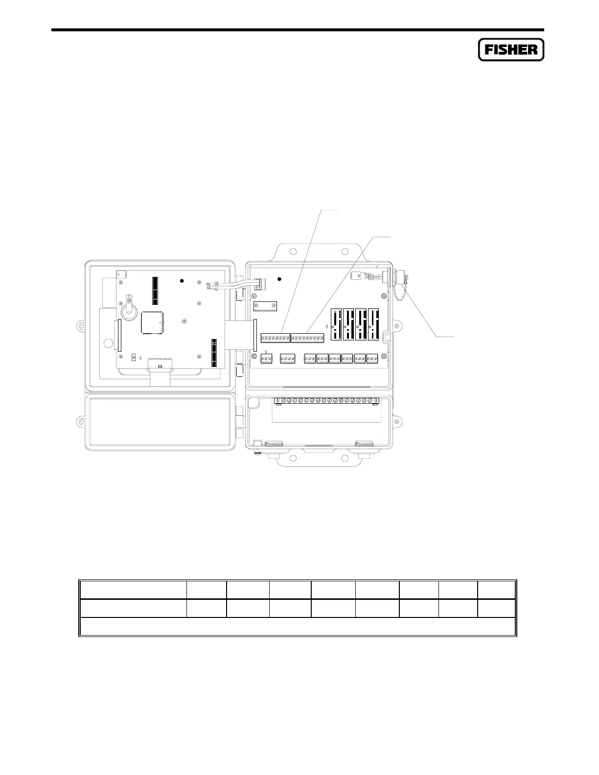
DOC0217A
COM1
COM2
OPERATOR
INTERFACE
PORT
Figure 2-9. Operator Interface, COM1, and COM2 Ports
Table 2-2. COM1 Port Signals
TERMINAL 1 2 3 4 5 6 7 8
COM1 Signal RXD TXD RTS CTS DCD DTR* DSR COM
*This signal is permanently enabled (connected to +10 Vdc).
The COM2 port provides communications access to an optional plug-in communications card. Section
4 details the types of communications cards available for the FloBoss 407 and has information on
connecting wiring to the COM2 connector.

 Loading...


