FloBoss 407 Instruction Manual
Rev 5/00 C-7
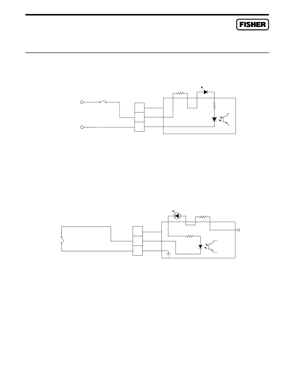
C.8 SWITCH TO PULSE INPUTS
Figure C-14 shows how to use a switch to simulate relay contacts to a pulse input source module.
AUX PWR OUT 1
-
SWITCH
+
C
B
-
+
A
N/C
R1=10
DOC0190A
PI ISO
2.2K
Figure C-14. Switch to PI Source Module
Figure C-15 shows how to use a switch and power supply to simulate a device transmitting discrete
pulses (turbine meter) to a pulse input isolated module.
SWITCH
R1=10
C
B
-
+
A
N/C
2.2K
DOC0189A
PI SRC
Vs
Figure C-15. Switch to PI Isolated Module

 Loading...


