FloBoss 407 Instruction Manual
3-18 Rev 5/00
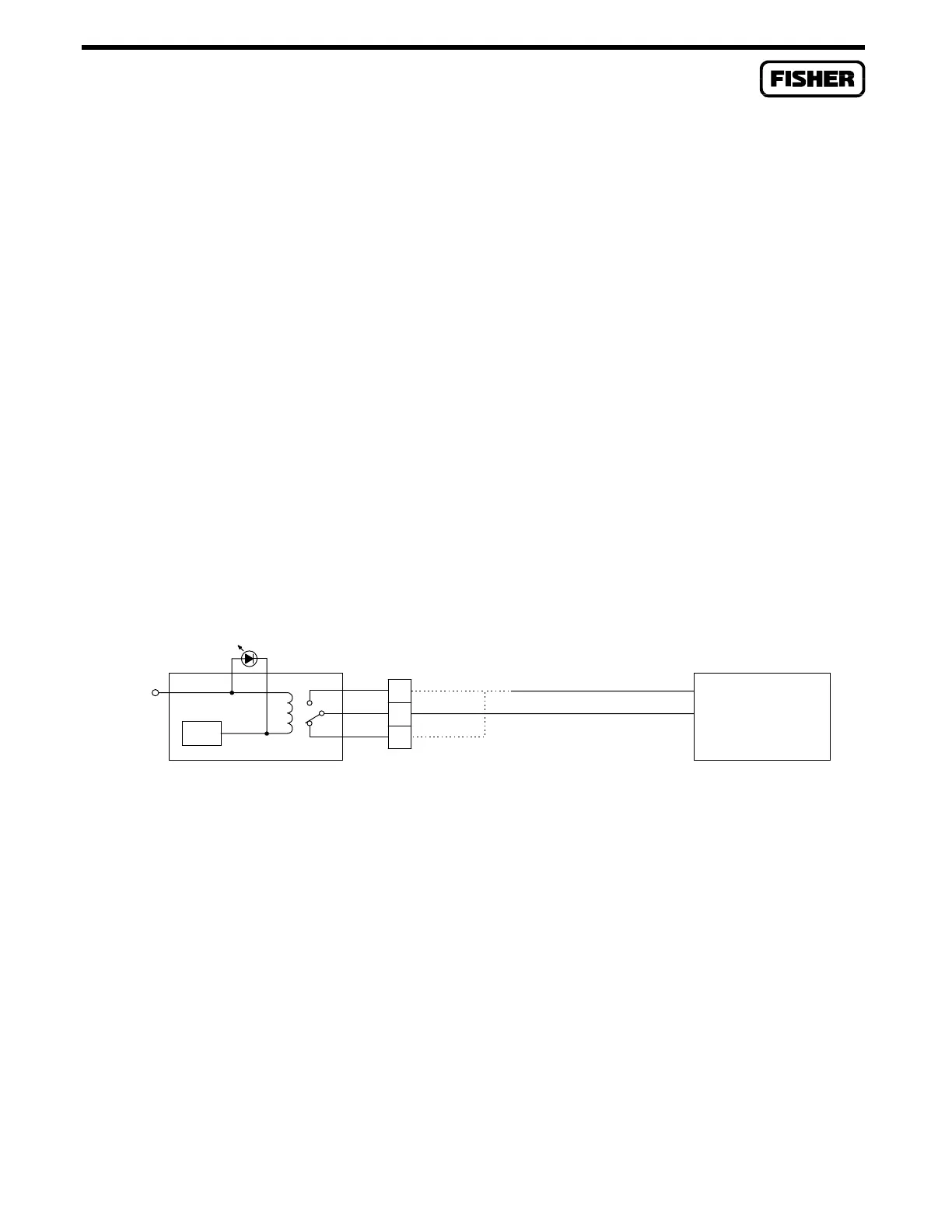
3.4.9 Discrete Output Relay Module
A schematic representation of the field wiring connections to the output circuit of the Discrete Output
Relay module is shown in Figure 3-15.
NOTE
The Discrete Output Relay module is designed to operate only with discrete
devices having their own power source. The module will be inoperative with
non-powered devices.
The Discrete Output Relay module operates by providing both normally-closed and normally-open
contacts to a field device. Normally-closed contacts use terminals B and C, and normally-open contacts
use terminals A and B. The status of the contacts (open or closed) is controlled by the ROC/FloBoss
software.
There are two versions of the relay module. The 12-volt version (which has a 12-volt energizing coil)
must be used when the ROC/FloBoss input voltage is a nominal 12 volts dc, and the 24-volt version
(which has a 24-volt energizing coil) must be used when the ROC/FloBoss input voltage is a nominal
24 volts dc.
TERMINAL A CONNECTION TO BE MADE FOR NORMALLY OPEN APPLICATIONS
TERMINAL B IS COMMON
TERMINAL C CONNECTION TO BE MADE FOR NORMALLY CLOSED APPLICATIONS
V
O
= VOLTAGE FROM DISCRETE DEVICE = 0 TO 30 VDC OR 0 TO 115 VAC, 5 A MAX
DO RLY
V
S
DOC0147A
CONTROL
COM
NC
NO
C
B
A
DISCRETE DEVICE
SELF-POWERED
+
V
O
Figure 3-15. Discrete Output Relay Module Field Wiring

 Loading...


