FloBoss 407 Instruction Manual
B-12 Rev 5/00
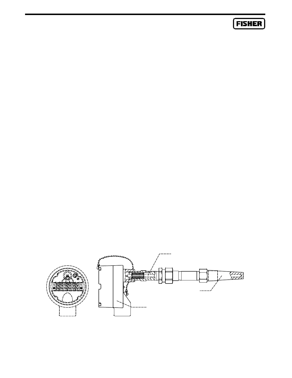
An RTD sensor assembly containing an element with an alpha of 0.00385 is available from Fisher
Controls (see Figure B-12). This sensor assembly is typically used with the MVS205. Refer to the
ROC/FloBoss Accessories Instruction Manual (Form A4637) for installation information.
If the MVS205 installation requires connection to an RTD sensor, install the sensor in the pipeline and
connect a prefabricated RTD cable to the MVS. The prefabricated RTD cable is keyed on the MVS end
and can be installed correctly only one way. The prefabricated RTD cable is available in a 12 or 24
foot length, either armored or not armored. The armored cable, which can be used in a Class I, Division
2 hazardous area, is non-incendiary and requires no conduit. The unarmored cable, which is normally
installed in conduit, must be used in Class I, Division 1 explosion-proof environments.
NOTE
In some cases, the installation of a FloBoss 407 with an integral MVS does not allow
front access to the RTD Cable Connector on the MVS (see Figure B-3). If you need
to access the RTD Cable Connector from the rear through the hole in the mounting
plate, remove the mounting plate, rotate the sensor body 180 degrees, remove the
four bolts on the bottom of the Coplanar flange (see Figure B-2) from the sensor
body, rotate the Coplanar flange 180 degrees, and reattach the Coplanar flange and
mounting plate. To meet CSA requirements, tighten the four bolts of the Coplanar
flange to the following torque specifications: 300 inch-pounds for SST bolts and 650
inch-pounds for carbon steel bolts.
To wire the RTD sensor to the MVS205, connect the stripped red and white leads (two of each color)
on the sensor end of the prefabricated RTD cable to the same color sensor wires inside the sensor
connection head (see Figure B-12). Connect the keyed connector end of the RTD cable to the MVS
body.
DOC0286R
Figure B-12. RTD Assembly Details
Thermowell
RTD element

 Loading...


