FloBoss 407 Instruction Manual
Rev 5/00 A-1
APPENDIX A — LIGHTNING PROTECTION MODULE
A.1 SCOPE
This appendix describes the Lightning Protection Module (LPM) used with Remote Operations
Controller (ROC) and FloBoss units. Topics covered include:
Information Section Page Number
Product Description A.2 A-1
Initial Installation A.3 A-2
Connecting the LPM to Wiring A.4 A-3
Troubleshooting and Repair A.5 A-4
Specifications A.6 A-4
A.2 PRODUCT DESCRIPTION
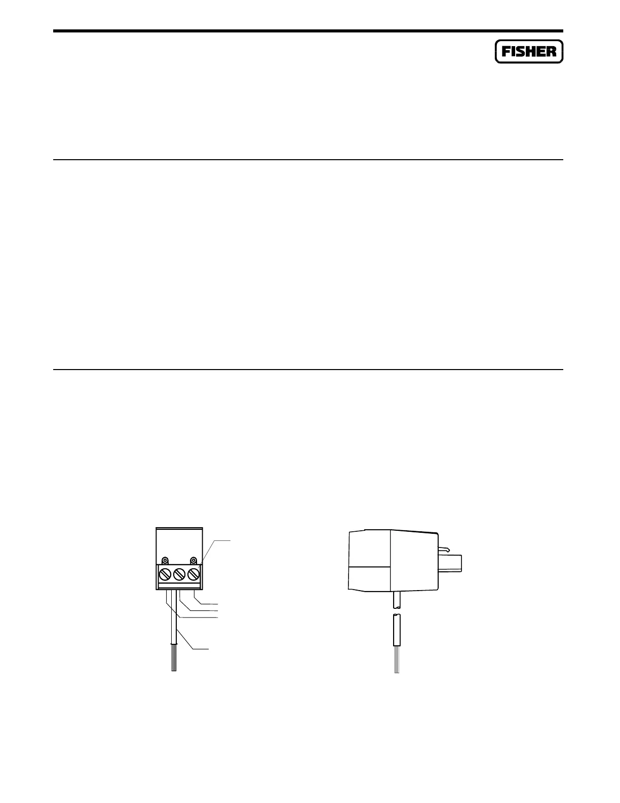
Figure A-1 shows a front and side view of the module. The LPM is designed to prevent damage to I/O
modules and to built-in I/O circuitry from any high-voltage transients that may occur in field wiring.
The LPMs plug into the field wiring I/O termination sockets located on the termination card.
The LPM provides screw terminals for connecting to field wiring. It has sockets for plugging in a range
resistor, especially when used with built-in I/O. The module also provides a ground wire for
connection to the enclosure ground bar.
Figure A-1. Lightning Protection Module
}
LPM-2
FRONT VIEW
BUILT-IN FIELD WIRING
TERMINATION BLOCK
CONNECT GREEN WIRE
TO ENCLOSURE GROUND
BAR OR GROUND LUG
I/O WIRING
DOC0138A
SIDE VIEW

 Loading...


