FloBoss 407 Instruction Manual
Rev 5/00 C-5
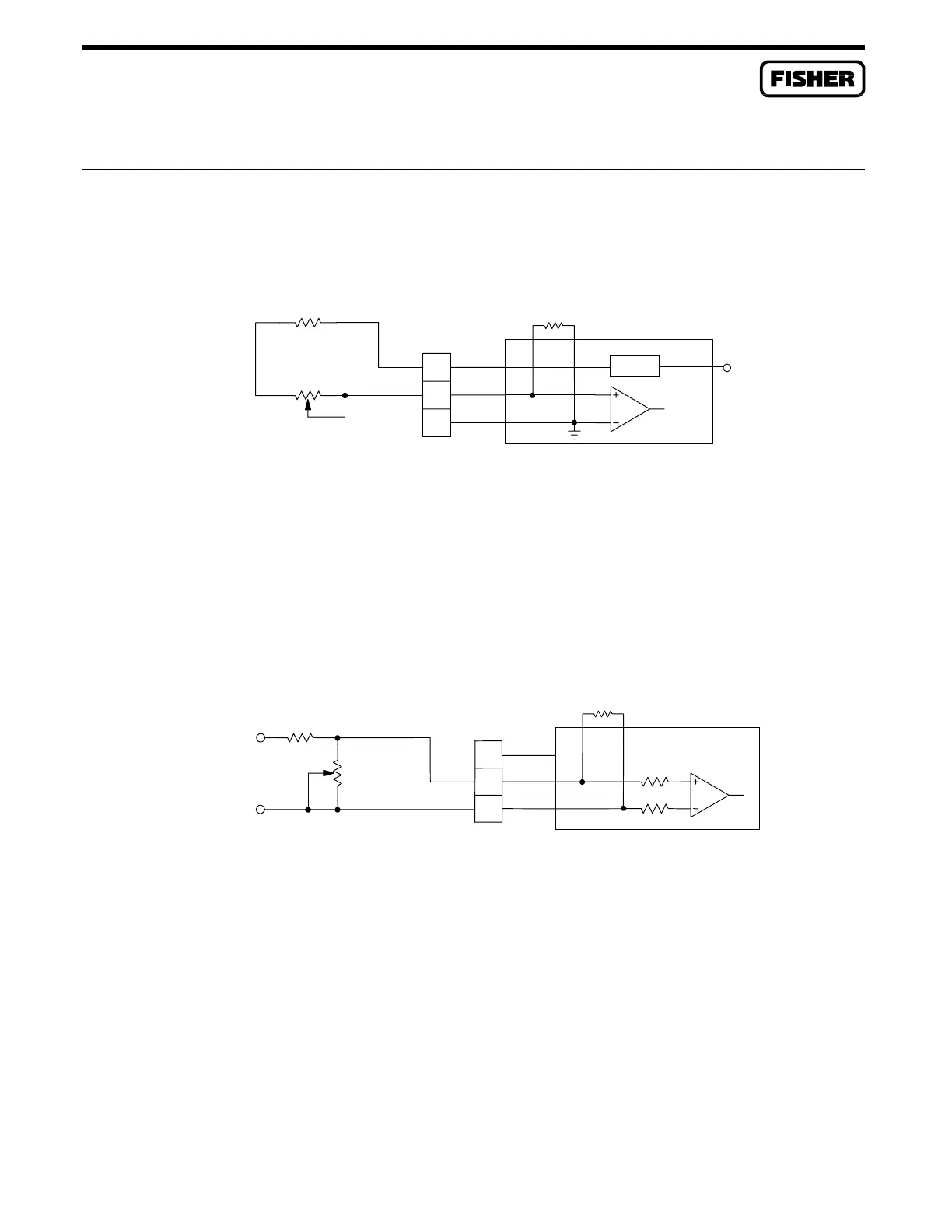
C.6 POTENTIOMETER TO ANALOG INPUTS
Figure C-10 shows how to use a potentiometer to simulate a transmitter feeding a 4 to 20 milliamp
current signal to an analog input loop module.
Vs = 24 VDC: R2 = 1K OHMS
Vs = 12 VDC: R2 = 390 OHMS
5K OHMS
R2
C
-
B
A
+
+T
R1=250
DOC0185A
I LIMIT
AI LOOP
Vs
Figure C-10. Potentiometer Input to AI Loop Module
Figure C-11 shows how to use a potentiometer and power source to simulate a transmitter feeding a
4 to 20 milliamp current signal to an analog input differential module.
UX PWR = 24 VDC
R2 = 20K OHMS
AUX PWR = 12 VDC, R2 = 8.2K OHMS
AUX PWR OUT 1
R2
-
+
5K OHMS
200K
200K
B
C
-
A
+
N/C
R1=OPEN
DOC0186A
AI DIFF
Figure C-11. Potentiometer Input to AI Differential Module

 Loading...


