FloBoss 407 Instruction Manual
Rev 5/00 3-11
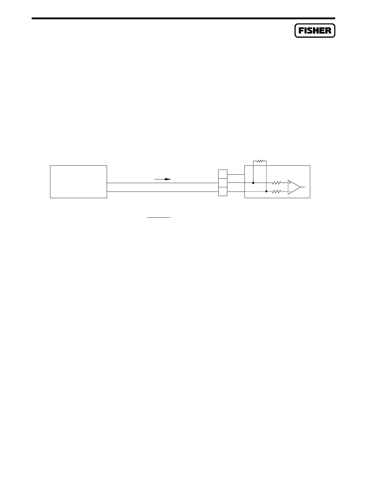
For current loop devices, scaling resistor R1 generates a voltage across terminals B and C that is
proportional to the loop current. When connecting current loop devices, the value of R1 must be
selected such that the 5-volt input limit of the module is not exceeded under maximum operating
current conditions. For 0 to 20 milliamp or 4 to 20 milliamp devices, the value of R1 would be 250
ohms. In this case, you can use the 250-ohm (0.1%, 1/8W) scaling resistor supplied by the factory. The
formula for determining the value of R1 is given in Figure 3-6, where “I Maximum” is the upper end of
the operating current range (such as 0.025 amps for a 0 to 25 milliamp device).
I
TO SELECT PROPER VALUE FOR R1:
V = VOLTAGE FROM ANALOG DEVICE = 0 TO 5 VDC
I MAXIMUM
SELF-POWERED
CURRENT LOOP
DEVICE
R1 =
o
–
V
o
+
5 VOLTS
DOC0154A
N/C
+
B
C
–
A
200K
200K
R1
AI DIFF
Figure 3-6. AI Differential Module Field Wiring for Current Loop Devices

 Loading...


