FloBoss 407 Instruction Manual
3-12 Rev 5/00
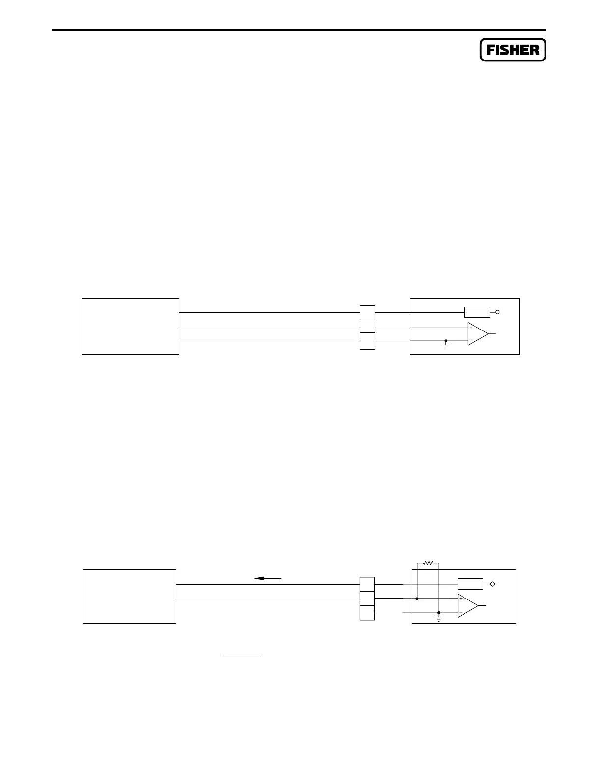
3.4.3 Analog Input Source Module
A schematic representation of the field wiring connections to the input circuit of the Analog Input
Source module is shown in Figure 3-7 and Figure 3-8. The AI Source module is normally used to
monitor the voltage output of low-voltage transmitters, but it can be used for monitoring loop current.
The module provides source power at terminal A for the loop. The Analog Input Source module
operates by measuring the voltage across terminals B and C. The module accepts a maximum input
voltage of 5 volts dc, which is the upper operating limit of the module.
Figure 3-7 shows a typical voltage signal input. Terminal B is the positive (+) signal input and terminal
C is the negative (-) signal input. These terminals accept a voltage signal in the 0 to 5 volt range. Since
terminal C connects to common, the analog input can only be a single-ended input. Make sure no
scaling resistor is installed when wiring the module for a voltage signal.
VOLTAGE DEVICE
ROC-POWERED
+10Vdc
+
+10Vdc
+
C
B
A
V SRC
I SRC
Vs
SIGNAL = 0 TO 5 Vdc
Figure 3-7. AI Source Module Field Wiring for Voltage Devices
The AI Source module can be used for monitoring loop current as shown in Figure 3-8. For current
loop monitoring, scaling resistor R1 generates a voltage across terminals B and C that is proportional to
the loop current (I). For example, a 250-ohm scaling resistor would accommodate either 0 to 20
milliamp, or 4 to 20 milliamp current loop transmitters (the transmitter must be able to operate on 10
volts dc or be powered from another source). This translates to a maximum operating input voltage of 5
volts dc, which is the upper limit of the module. When using a transmitter with a maximum operating
current requirement different than 20 milliamps, R1 should be sized to achieve full scale deflection at 5
volts. The formula for determining a new value of R1 is given in Figure 3-8.
I
CURRENT LOOP
DEVICE
ROC-POWERED
TO SELECT PROPER VALUE OF R1:
Vs = SOURCE VOLTAGE FROM MODULE = 10 Vdc, 20 mA MAX
+
+10 Vdc
B
I MAXIMUM
R1 =
5 VOLTS
C
A
+
R1
V SRC
I SRC
Vs
Figure 3-8. AI Source Module Field Wiring for Current Loop Devices

 Loading...


