FloBoss 407 Instruction Manual
Rev 5/00 3-15
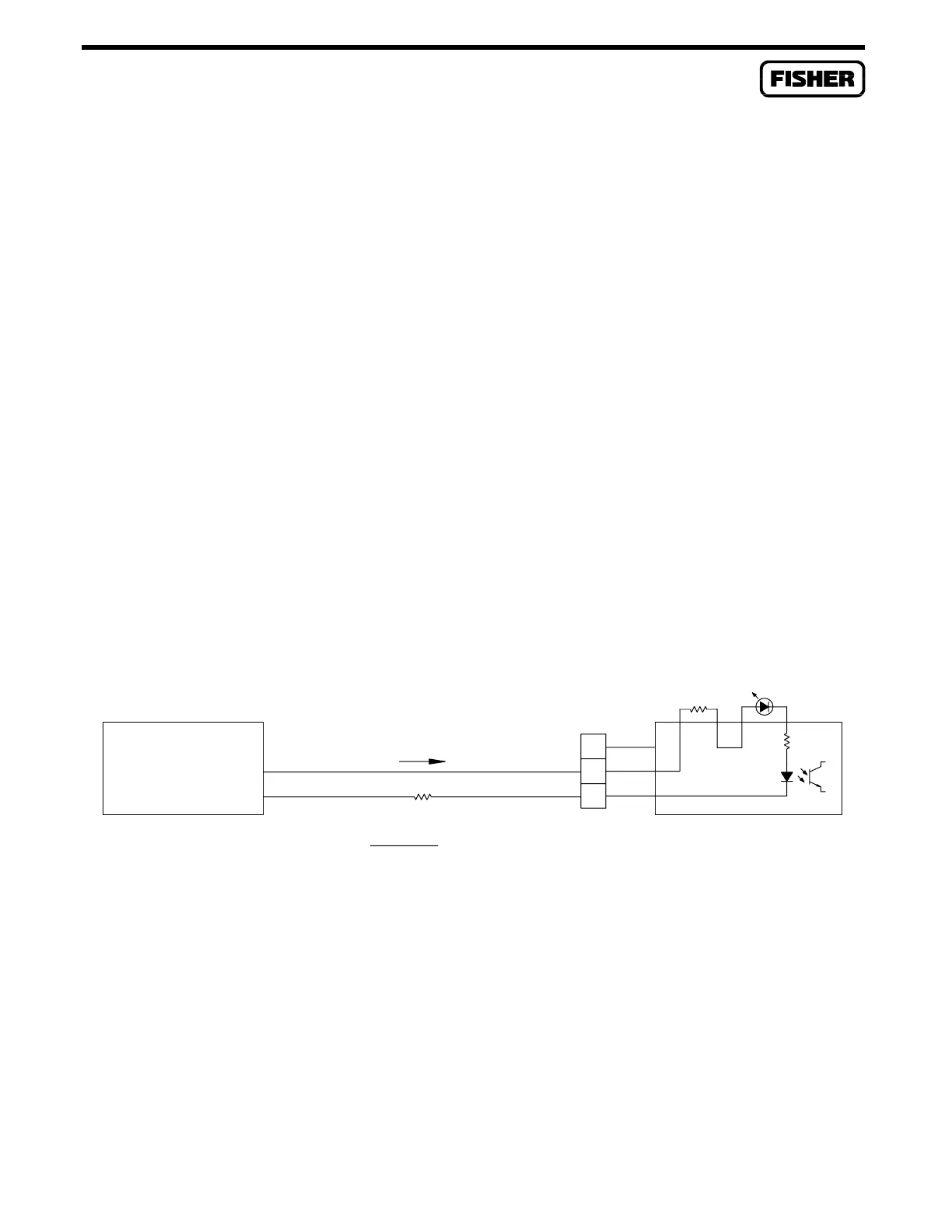
3.4.6 Discrete Input Isolated Module
A schematic representation of the field wiring connections to the input circuit of the Discrete Input
Isolated module is shown in Figure 3-12.
NOTE
The Discrete Input Isolated module is designed to operate only with discrete
devices having their own power source such as “wet” relay contacts or
two-state devices providing an output voltage. The module is inoperative
with non-powered devices.
The Discrete Input Isolated module operates when a field device provides a voltage across terminals B
and C of the module. The voltage sets up a flow of current sensed by the module which, in turn, signals
the ROC/FloBoss electronics that the field device is active. When the field device no longer provides a
voltage, current stops flowing and the DI module signals the ROC/FloBoss electronics that the device is
inactive.
A 10-ohm scaling resistor (R1) is supplied by the factory and accommodates an external voltage (V
o
) of
11 to 30 Volts dc. However, it is desirable to optimize the value of R1 to reduce the current drain from
the source or reduce the heat generated in the module due to high source voltage. The formula for
determining the optimum value of R1 is given in Figure 3-12. For best efficiency, R1 should be scaled
for a loop current (I) of 3 milliamps.
–
+
SELF-POWERED
DISCRETE DEVICE
3.3K
N/C
R1 + R
W
+ 3.3K = LOOP RESISTANCE = 4.5K OHMS MAX
V
O
= VOLTAGE FROM DISCRETE DEVICE = 11 TO 30 VDC
I = LOOP CURRENT = 3 mA TYPICAL
TO OPTIMIZE SCALING RESISTOR R1:
R
W
= RESISTANCE OF FIELD WIRING
R
W
– 3.3KR1 =
V
O
V
O
– 1
I
R
W
B
C
A
+
DOC0144A
R1=10
DI ISO
I
Figure 3-12. Discrete Input Isolated Module Field Wiring

 Loading...


