FloBoss 407 Instruction Manual
Rev 5/00 4-17
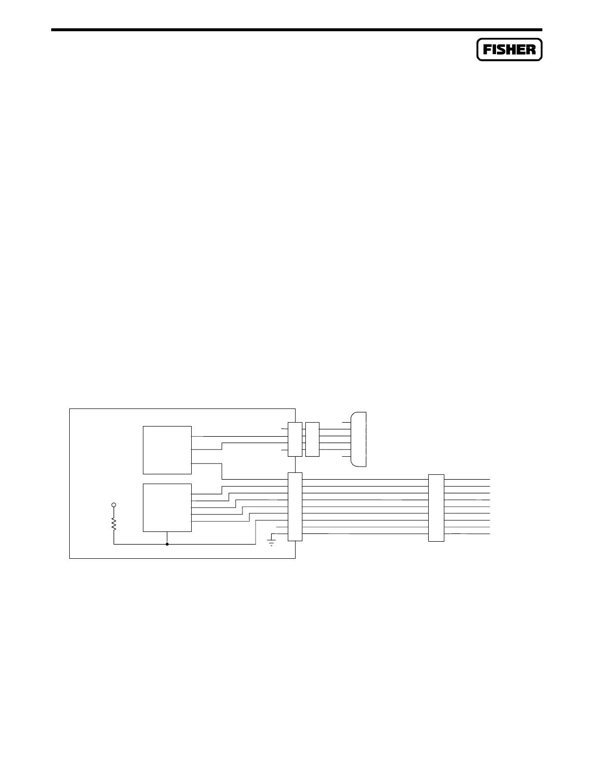
4.4.5 Dial-Up Modem Communications Card Wiring
The dial-up modem card interfaces to a PSTN line through the RJ11 jack with two wires. The RJ11
terminal functions are as follows:
RJ11 OPERATING MODE
TERMINAL (2-Wire)
GRN Ring
RED Tip
Figure 4-12 shows the relationship between the dial-up modem signals and pin numbers for the
RJ11 connector and the COM2 connectors.
CAUTION
Care should be exercised to avoid shorting the +5 VDC supply (terminal 6 on the
COM2 terminal block) to common (terminal 9) or to any ground when wiring to
COM2. Grounding terminal 6 causes the ROC/FloBoss to halt operation and
data may be lost once a restart is initiated.
DIAL-UP MODEM CARD
INTERFACE
TTL/RS232
MODEM
20
15
RXD
DSR
RI
DTR
TXD
SPK
TIP
RING
24
22
19
18
17
21
23
1
4
3
2
4
2
1
3
RED
YEL
GRN
BLK
+5V
DOC0216T
SHUTDOWN
RI
TXD
DSR
DTR
RXD
SPK
P3
P2
COM
COM2
TERMINAL
BLOCK
6
9
2
4
7
8
3
5
1
RJ11
PSTN
SHUTDOWN
NC
NC
10K
+5V
+5V
6
3
4
1
2
5
Figure 4-12. Dial-Up Modem Wiring Schematic
The following signals (output only) are available at the COM2 port for wiring to an analyzer or
monitor. These signals are activated by shorting pin 4 (SHUTDOWN) to pin 9 (COM).

 Loading...


